State of charge calculation device and state of charge calculation method

a state of charge and calculation device technology, applied in the direction of transportation and packaging, testing electric installations on transportation, instruments, etc., can solve the problems of deteriorating accuracy of soc estimate, not resuming soc correction, and discharge level, etc., to achieve high degree of accuracy

Inactive Publication Date: 2005-01-18
TOYOTA JIDOSHA KK
View PDF9 Cites 42 Cited by
  • Summary
  • Abstract
  • Description
  • Claims
  • Application Information

AI Technical Summary

Benefits of technology

It is an object of the invention to provide an SOC calculation device and an SOC calculation method for a battery which can ensure that SOC is estimated with a high degree of accuracy, without depending on the battery charge and discharge level.
Moreover, it is a further objective of the invention to provide an SOC calculating device and an SOC calculating method capable of accurately calculating the SOC of a secondary battery by correcting the SOC estimate, based on a period in which the battery discharges to a load.

Problems solved by technology

This is because, accuracy is strongly influenced, for example, by errors resulting from the omission of LSB digits of the CPU for calculating the SOC, or a fall in charge due to self-discharge.
In addition, charge and discharge levels which cause the accuracy of the SOC estimate to deteriorate, are mainly within the normal usage range of the battery.
Furthermore, SOC correction is not resumed until the corrected SOC has departed from a predetermined region.
However, if the secondary battery naturally discharges, the SOC reduces.

Method used


Image

  • State of charge calculation device and state of charge calculation method
  • State of charge calculation device and state of charge calculation method
  • State of charge calculation device and state of charge calculation method

Examples


first embodiment

Hereinafter, a preferred first embodiment according to the invention will be described referring to FIG. 1 to FIG. 6, in order to clarify the invention in further detail.

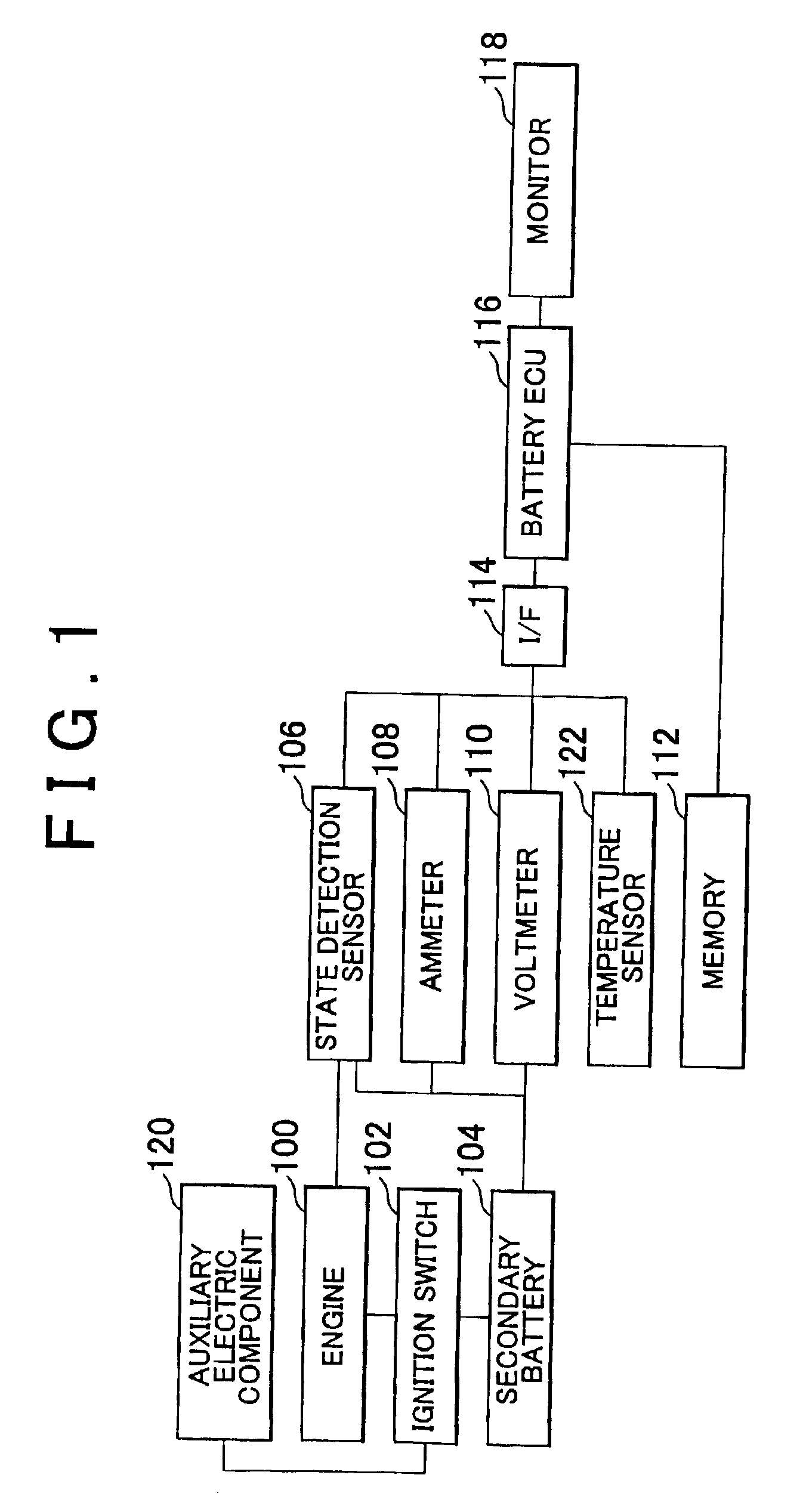
FIG. 1 shows a block diagram of the control of a vehicle including an SOC calculation device according to the first embodiment of the invention. The vehicle includes an engine 100, an auxiliary electric component 120, an ignition switch (hereinafter referred to as “I / G switch”) 102, a secondary battery 104, a state detection sensor 106, an ammeter 108, a voltmeter 110, a memory 112, an interface (hereinafter referred to as “I / F”) 114, a battery electronic control unit (hereinafter referred to as “battery ECU”) 116, a monitor 118, and a temperature sensor 122.

The engine 100 and the auxiliary electric component 120 are connected to the secondary battery 104 via the I / G 102. The auxiliary electric component 120 is, for example, a car audio device or an air conditioner. The secondary battery 104 is connected to the stat...


PUM


Abstract

A state of charge calculation device includes an ammeter for detecting charge and discharge currents of a secondary battery, a state detection sensor for detecting a start time of discharge from the secondary battery to an engine, a battery electronic control unit (ECU) for calculating a state of charge of the secondary battery. The battery ECU of this state of charge calculation device calculates the state of charge of the secondary battery, based on the current and voltage detected at the time when discharge starts.

Description

INCORPORATION BY REFERENCEThe disclosures of Japanese Patent Applications No. 2001-352033 filed on Nov. 16, 2001, and No. 2002-45028 filed on Feb. 21, 2002, each including the specification, drawings and abstract is incorporated herein by reference in its entirety.BACKGROUND OF THE INVENTION1. Field of the InventionThis invention relates to a state of charge calculation device and a state of charge calculation method2. Description of the Related ArtA secondary battery is used as a main or auxiliary power source in various fields such as automobiles, hybrid vehicles and electric carts. In order to operate this secondary battery efficiently, it is necessary to accurately execute charge and discharge control. Accordingly, a method for accurately calculating the state of charge (hereinafter referred to as “SOC”) of the secondary battery is required.A method which uses current integration of charge and discharge currents has been known as a method for calculating the SOC of a secondary b...

Claims


Application Information

Patent Timeline
Patent Type & Authority Patents(United States)
IPC IPC(8): G01R31/36G01R31/00
CPCG01R31/3648G01R31/3624G01R31/006G01R31/3842
Inventor TERUO, ISHISHITA
Owner TOYOTA JIDOSHA KK
Why Eureka
Try Eureka