Refrigeration apparatus

Inactive Publication Date: 2005-01-25
DAIKIN IND LTD
View PDF16 Cites 10 Cited by
  • Summary
  • Abstract
  • Description
  • Claims
  • Application Information

AI Technical Summary

Benefits of technology

The object of the present invention is to make it possible to always obtain the optimum refrigerant charging amount by making it possible to charge the amount of refrigerant that the refrigeration apparatus requires at the time of the onsite installation.
Thus, for example, if the apparatus is configured such that it can be detected when the liquid surface reaches a maximum liquid level (Lmax), then overcharging of refrigerant into the refrigerant circuit can be detected. Furthermore, even when the length of the liquid pipe, gas pipe, and other connecting piping cannot be measured, the required amount of refrigerant charging can be obtained easily by detecting when a prescribed liquid level (L0) is obtained inside the receiver.
Since the liquid level detecting means of this refrigeration apparatus comprises a temperature detecting means and a bypass circuit that includes an ON / OFF valve and a pressure reducing mechanism, the liquid level can be detected reliably at low cost.
With this refrigeration apparatus, the refrigerant circuit is charged with refrigerant while a refrigerant charging operation state is created in which the refrigerant circuit is filled with liquid refrigerant having a prescribed density. During this refrigerant charging operation, refrigerant charging is ended when it is detected that the liquid surface inside the receiver has reached a prescribed level. Thus, the reliability of the refrigerant charging process is improved.
With this refrigeration apparatus, collection of more liquid refrigerant than is necessary in the heat-source-side heat exchanger (which acts as the condenser) is avoided and the gas pipe disposed between the utilization-side heat exchanger and the suction side of the compressor is filled with gaseous refrigerant. Therefore, a refrigerant charging operation state in which the liquid piping is filled with liquid refrigerant having a prescribed density can be achieved easily.

Problems solved by technology

When the refrigerant charging amount is determined onsite during installation, the performance and reliability of the equipment becomes dependent on the quality of the installation and, in some cases, the maximum capacity of the refrigeration apparatus cannot be realized.

Method used


Image

  • Refrigeration apparatus
  • Refrigeration apparatus
  • Refrigeration apparatus

Examples


Embodiment Construction

Below, preferred embodiments of the present invention are described while referring to the attached drawings.

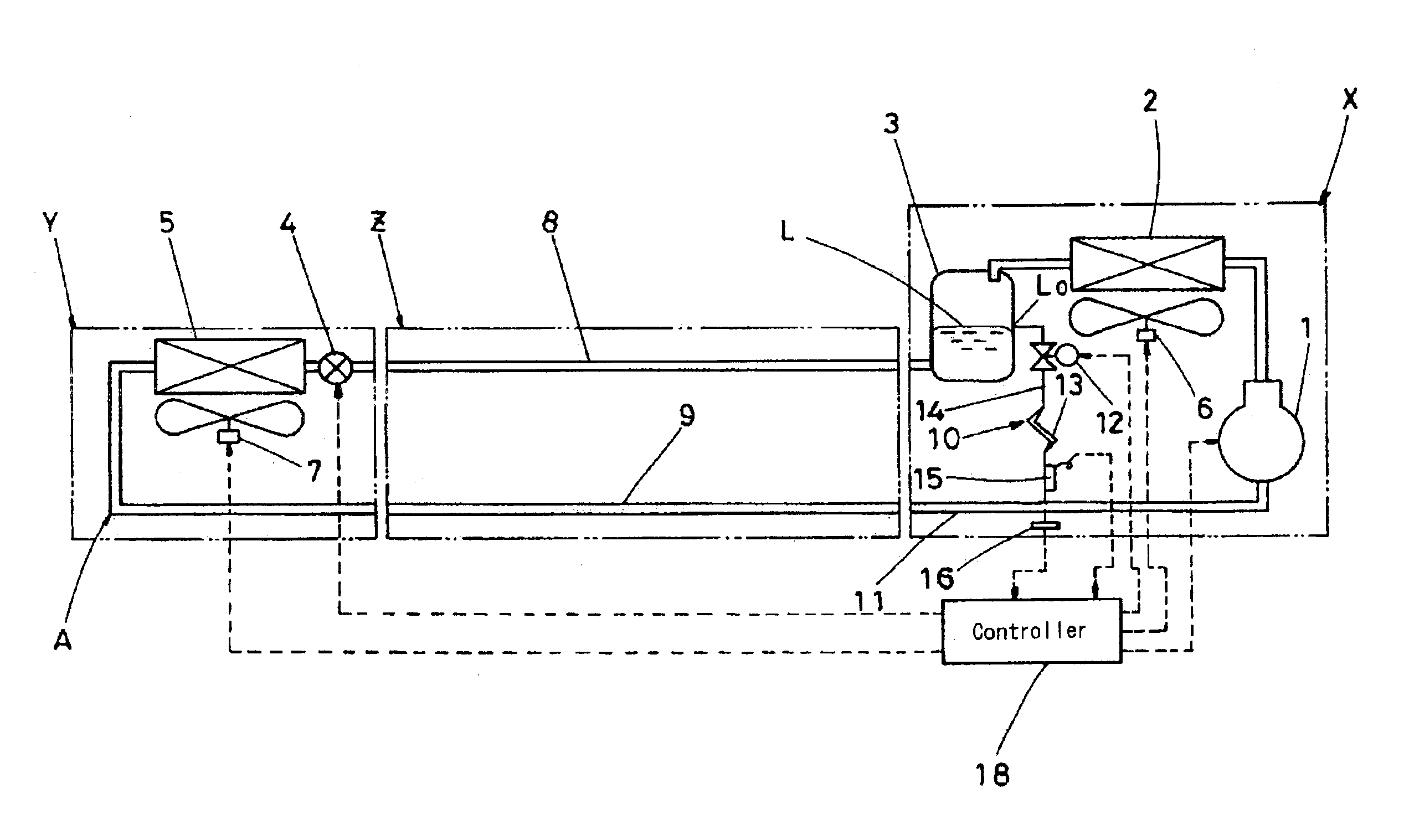
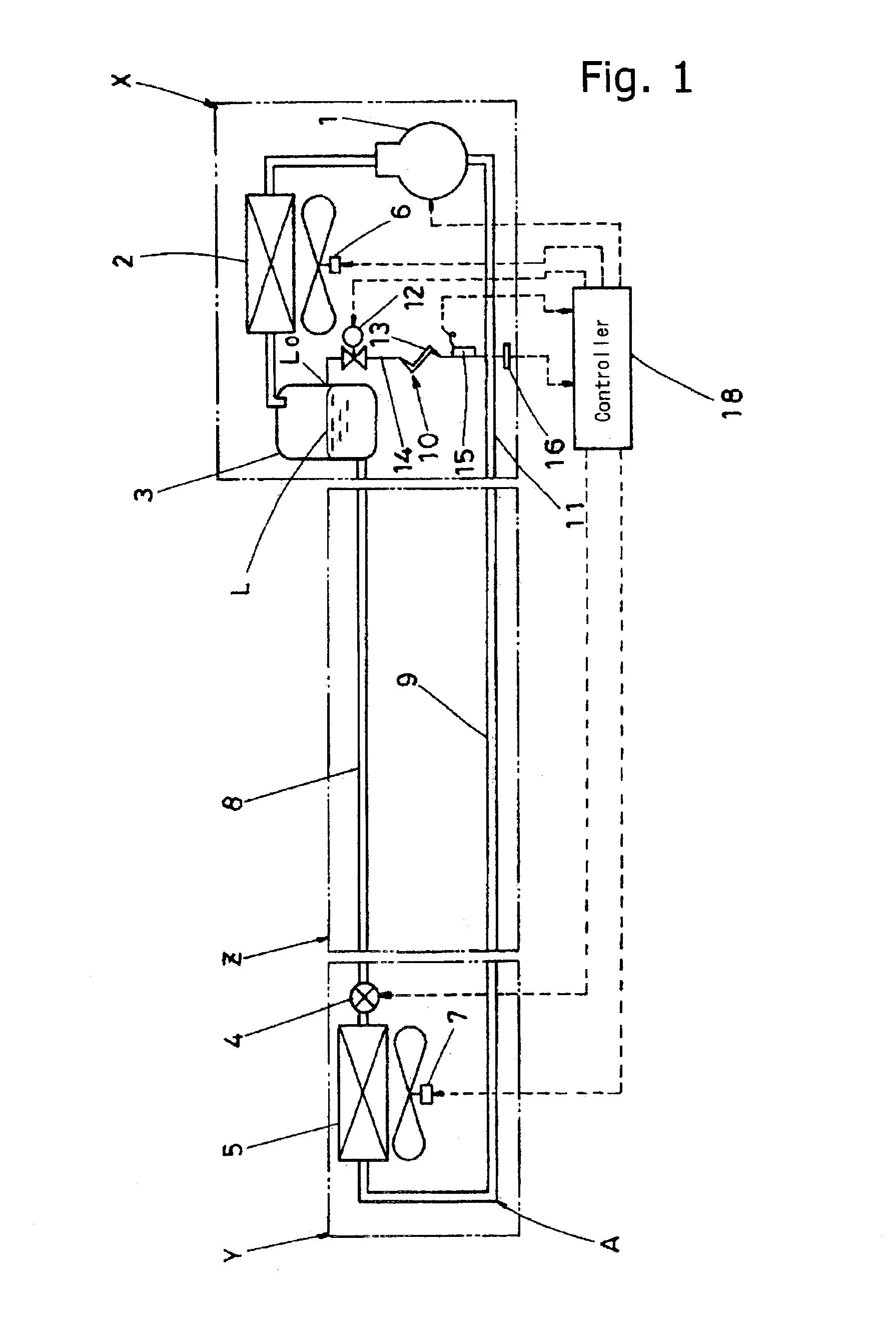
As shown in FIG. 1, this split-type refrigeration apparatus comprises an outdoor unit X and an indoor unit Y. The outdoor unit is equipped with a compressor 1, an air-cooled condenser 2 (heat-source-side heat exchanger) combined with an outdoor fan 6, and a receiver 3. The indoor unit is equipped with an expansion valve 4 and an evaporator 5 (utilization-side heat exchanger). The outdoor unit and indoor unit are connected by a liquid pipe 8 and a gas pipe 9 to form a refrigeration cycle A (refrigerant circuit). Liquid pipe 8 and gas pipe 9 include an onsite piping section Z. Item 7 is an indoor fan.

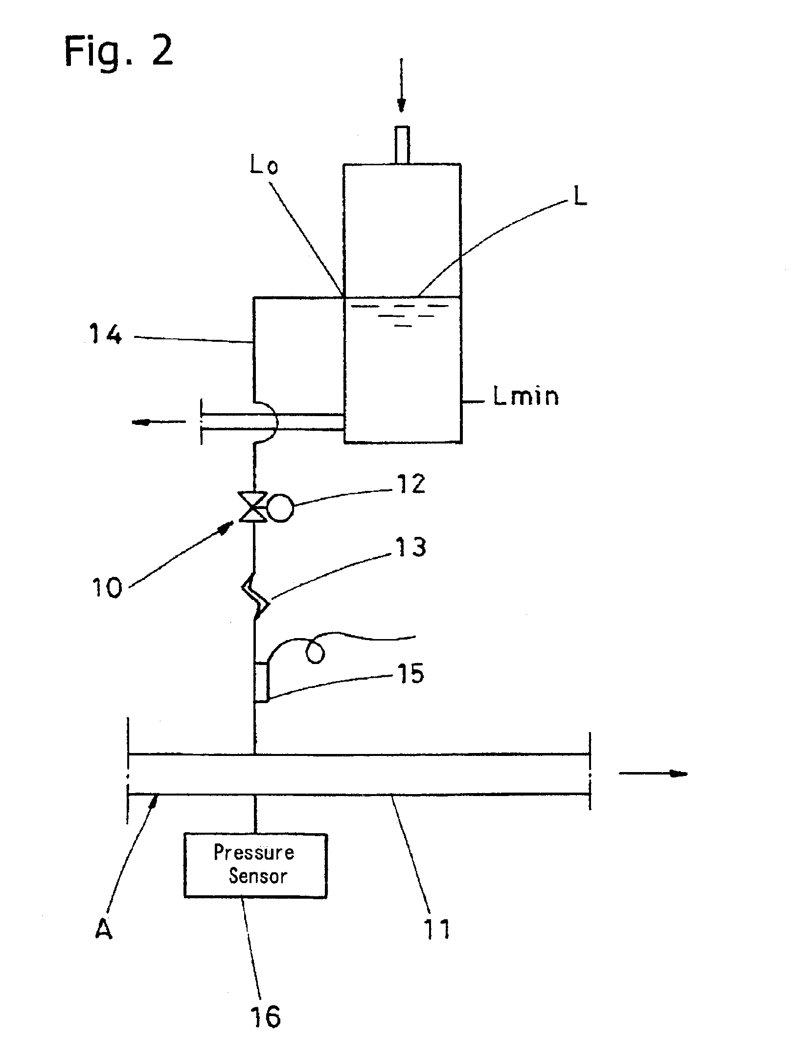
As shown in FIG. 2, receiver 3 is equipped with a liquid level detecting means or member 10 that detects if the liquid surface level L has reached a prescribed level L0 inside receiver 3. In this embodiment, liquid level detecting member 10 comprises a bypass circuit 14 and a therm...


PUM


Abstract

This invention makes it possible to charge a refrigeration apparatus with the amount of refrigerant that the refrigeration apparatus requires at the time of onsite installation. As a result, the optimum refrigerant charging amount can always be obtained. The refrigeration apparatus is provided with a refrigeration cycle in which an outdoor unit equipped with a compressor, a condenser, and a receiver is connected to an indoor unit equipped with an expansion valve and an evaporator via a liquid pipe and a gas pipe. The refrigeration cycle is charged with refrigerant while a refrigerant charging operation state is created in which the liquid pipe that connects the outdoor unit to the indoor unit is filled with liquid refrigerant having a prescribed density. Refrigerant charging ends when, during the refrigerant charging operation, it is detected that the level of the liquid inside the receiver has reached a prescribed level.

Description

TECHNICAL FIELDThe present invention relates to a split-type refrigeration apparatus. More specifically, the present invention relates to a method of setting and determining the refrigerant charging amount when a split-type refrigeration apparatus is charged with refrigerant onsite.BACKGROUND ARTSplit-type refrigeration apparatuses comprising an outdoor unit equipped with a compressor, a condenser, and a receiver and an indoor unit equipped with an expansion valve and an evaporator are well known. The refrigerant charging of split-type refrigeration apparatuses configured in this manner has conventionally been handled by charging the outdoor unit with a prescribed amount of refrigerant in advance and charging additional refrigerant onsite in accordance with the length of the piping connecting the outdoor unit to the indoor unit when the apparatus is installed.When the refrigerant charging amount is determined onsite during installation, the performance and reliability of the equipme...

Claims


Application Information

Patent Timeline
IPC IPC(8): F25B49/02F25B45/00F25B1/00
CPCF25B45/00F25B49/027F25B2400/16F25B2600/02Y02B30/743F25B2600/112F25B2600/2513F25B2700/04F25B2700/1933F25B2600/111Y02B30/70
Inventor MATSUOKA, HIROMUNESHIMODA, JUNICHI
Owner DAIKIN IND LTD
Why Eureka
Try Eureka