Oil pan with vertical baffles for oil flow control

a technology of oil pan and vertical baffle, which is applied in the direction of machine/engine, lubrication of auxiliaries, combustion air/fuel air treatment, etc., can solve the problem of dragging the oil back into the sump for redistribution, and achieve the effect of reducing the quantity of oil required, the cost and weight of the oil pan

Active Publication Date: 2005-01-25
GM GLOBAL TECH OPERATIONS LLC
View PDF10 Cites 52 Cited by
  • Summary
  • Abstract
  • Description
  • Claims
  • Application Information

AI Technical Summary

Benefits of technology

The present invention provides an improved oil pan which eliminates the need for a horizontal baffle, thereby enabling a one

Problems solved by technology

The horizontal baffle is effective in limiting “sloshing” of oil during high acceleration man

Method used


Image

  • Oil pan with vertical baffles for oil flow control
  • Oil pan with vertical baffles for oil flow control
  • Oil pan with vertical baffles for oil flow control

Examples


Embodiment Construction

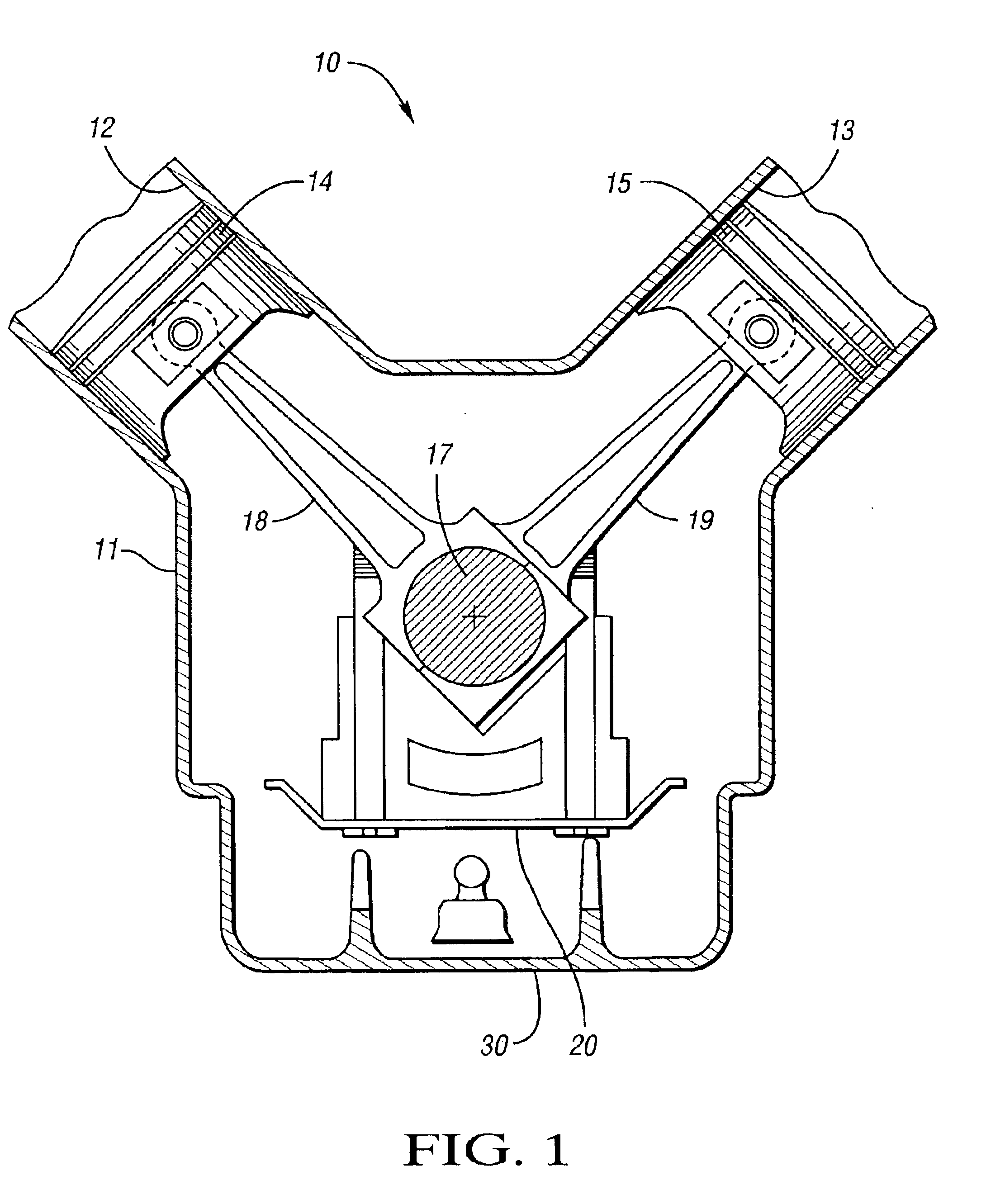
FIG. 1 shows an engine 10 including a cylinder block 11 having a plurality of cylinders 12, 13 that house a plurality of pistons 14, 15, respectively. The engine also includes a crankshaft 17 that is connected to the pistons 14, 15 by connecting rods 18, 19, respectively. The crankshaft 17 is rotatable with respect to the cylinder block 11 so as to cause the pistons 14, 15 to reciprocate in the cylinders 12, 13.

Rotation of the crankshaft 17 causes air to rotate with the crankshaft. This rotating air may be referred to as “crankshaft windage.” During operation of the engine, some oil that would otherwise drain into the oil pan may instead become entrained in the crankshaft windage. Accordingly, the engine 10 further includes the crankshaft oil deflector 20 which is operative to remove oil from the crankshaft windage and drop the oil into the oil pan 30.

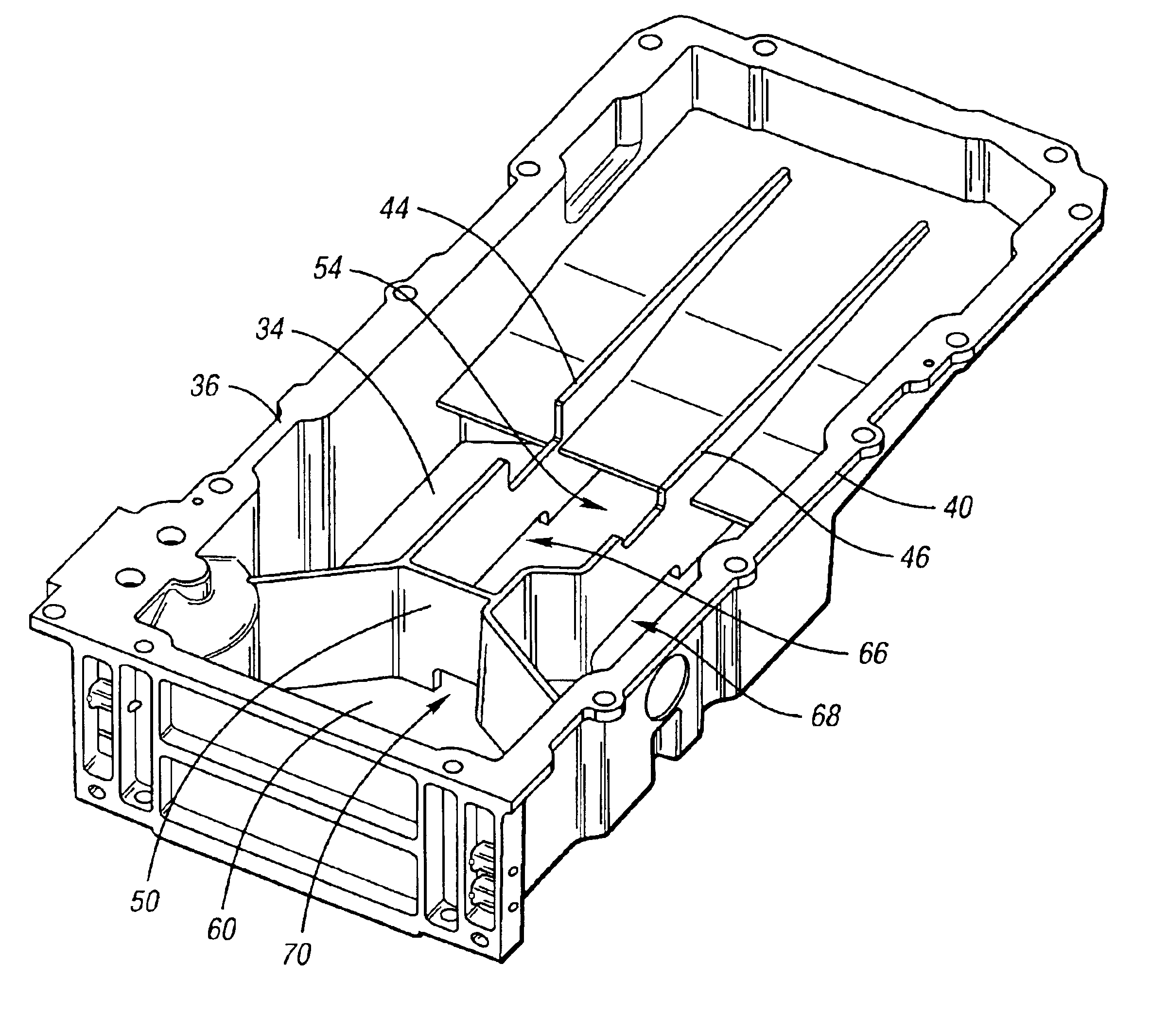
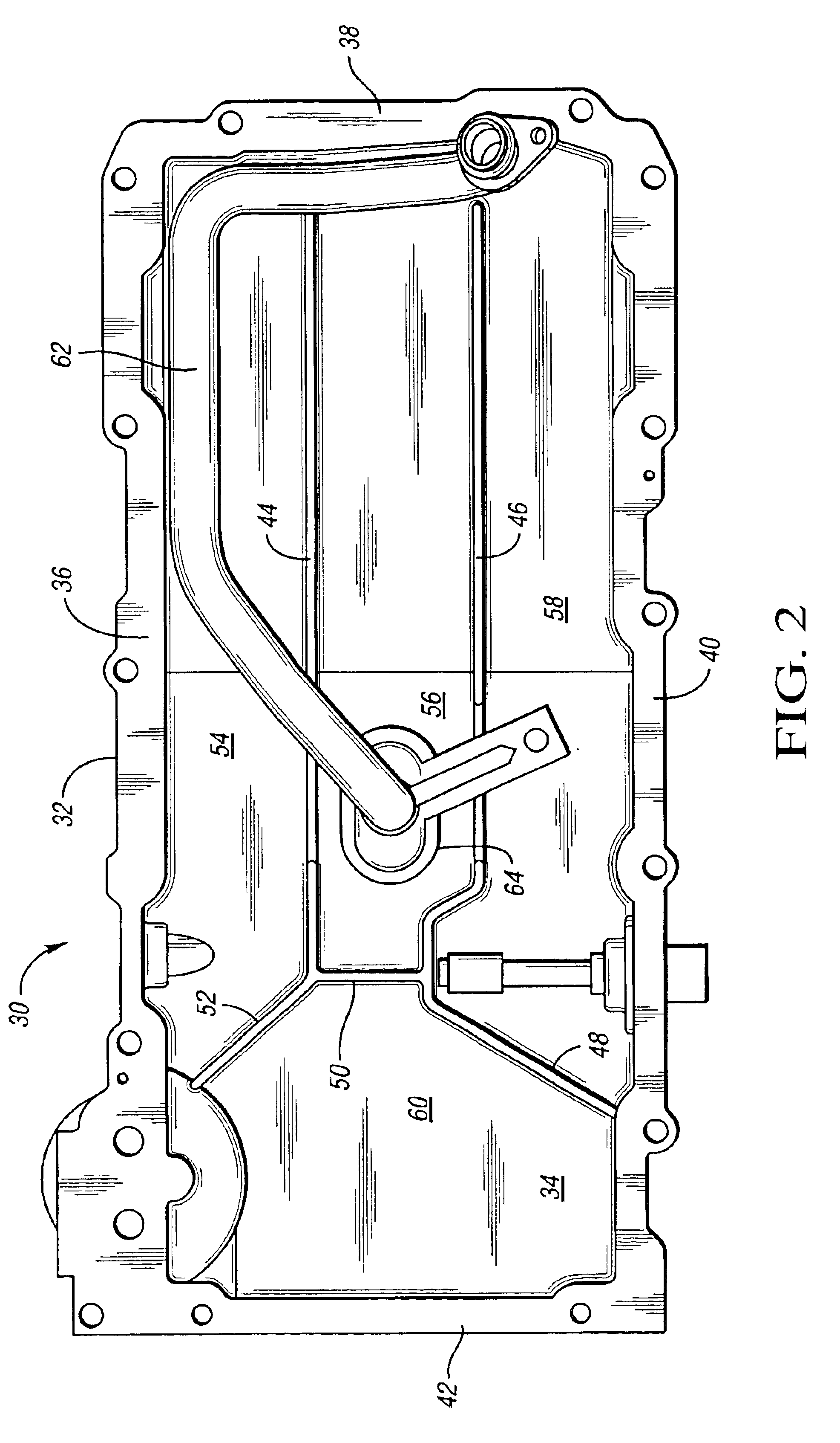
The oil pan 30 is shown in greater detail in FIGS. 2-4. As shown, the oil pan 30 is preferably a one-piece cast aluminum component an...


PUM


Abstract

An oil pan for an engine includes a body having a floor and side walls. The body has a plurality of baffles extending vertically from the floor and intersecting each other and the side walls in a manner to form four chambers. The baffles have openings to allow oil flow therethrough. One of the chambers acts as an oil pick-up chamber.

Description

TECHNICAL FIELDThe present invention relates to an oil pan having a plurality of vertical baffles which divide the oil pan into four chambers to limit oil movement during high acceleration vehicle maneuvers.BACKGROUND OF THE INVENTIONA typical oil pan is disposed beneath a cylinder block and crank shaft of an internal combustion engine. Such an oil pan is configured to receive oil that drains or is otherwise exhausted from the cylinder block and the crank shaft and / or main bearings that support the crank shaft. The oil collects in a sump of the oil pan and is then pumped from a sump pick-up location into a lubrication system associated with the engine. The oil pan may also be provided with a horizontal baffle that inhibits oil from moving away from the pick-up location during high acceleration (i.e., “high G”) vehicle maneuvers, such as sudden turning, acceleration, or braking events.The horizontal baffle may require a two-piece construction of the oil pan. The horizontal baffle is ...

Claims


Application Information

Patent Timeline
IPC IPC(8): F01M11/00
CPCF01M11/0004F01M2011/005F05C2201/021F01M2011/0091F01M2011/007
Inventor BISHOP, THOMAS M.
Owner GM GLOBAL TECH OPERATIONS LLC
Why Eureka
Try Eureka