Telescopic stick

a telescopic stick and telescopic technology, applied in the field of telescopic sticks, can solve the problems of increasing inaccurate and inconvenient operation, and telescopic sticks b>10/b> also pose a danger to children in the household, so as to save materials and processing costs, accurate and easy operation of telescopic sticks, and the effect of saving the cost of materials and processing

Inactive Publication Date: 2005-01-25
CHING FENG BLINDS INC CO LTD
View PDF18 Cites 65 Cited by
  • Summary
  • Abstract
  • Description
  • Claims
  • Application Information

AI Technical Summary

Benefits of technology

It is, therefore, the primary purpose of the present invention to provide a telescopic stick, including a retaining mount, a supporting sleeve, an inner tube and an outer tube, which is reduced in assembly parts, economically saving the costs of materials and processing as well as facilitating a fast and easy assembly thereof.
It is, therefore, the secondary purpose of the present invention to provide a telescopic stick wherein the inner and outer tubes are adjusted of length by either pushing or pulling thereof in horizontal direction to withdraw or extend the telescopic stick to suit the width of a door / window frame, facilitating an accurate and easy operation of the telescopic stick in adjustment thereof.
It is, therefore, the third purpose of the present invention to provide a telescopic stick wherein the supporting sleeve is led to a base of the retaining mount screwed up to the wall of the window / door frame from top to bottom, pressing downwards a resilient stop block of the base thereof to tightly abut against the upper surface of the supporting sleeve till a circular registration recess and an engagement ring of the supporting sleeve thereof engaged with an arc registration rib and an engagement cavity of the base thereof respectively for secure location of the supporting sleeve and both ends of the engaged inner and outer tubes thereto, preventing the inner and outer tubes from coming off there-from when pushed or pulled by outer force.

Problems solved by technology

There are some drawbacks to such conventional telescopic stick 10.
First, the assembly parts of the telescopic stick 10 are uneconomically numerous and complex in assembly, which increase not only the cost of materials but also that of processing as well.
Thus, it's quite inaccurate and inconvenient in terms of operation thereof.
Thus, besides the trouble of reassembly, the telescopic stick 10 also poses a danger to children in the household.
There are some disadvantages to the second conventional telescopic stick 20.
First, the assembly parts of the telescopic stick 20 are numerous and complex in assembly, uneconomically increasing the costs of materials and processing as well.
Second, the telescopic stick 20 is uncertainly rotated either clockwise or counterclockwise to adjust its length to suit the width of a door / window frame A, which is quite troublesome and inconvenient in operation thereof.
Once influenced by outer force such as pulled by children, the telescopic stick 20 can easily come off from the wall thereof, which, besides the trouble of reassembly, is insecurely unsafe to children in the household.

Method used


Image

  • Telescopic stick
  • Telescopic stick
  • Telescopic stick

Examples


Embodiment Construction

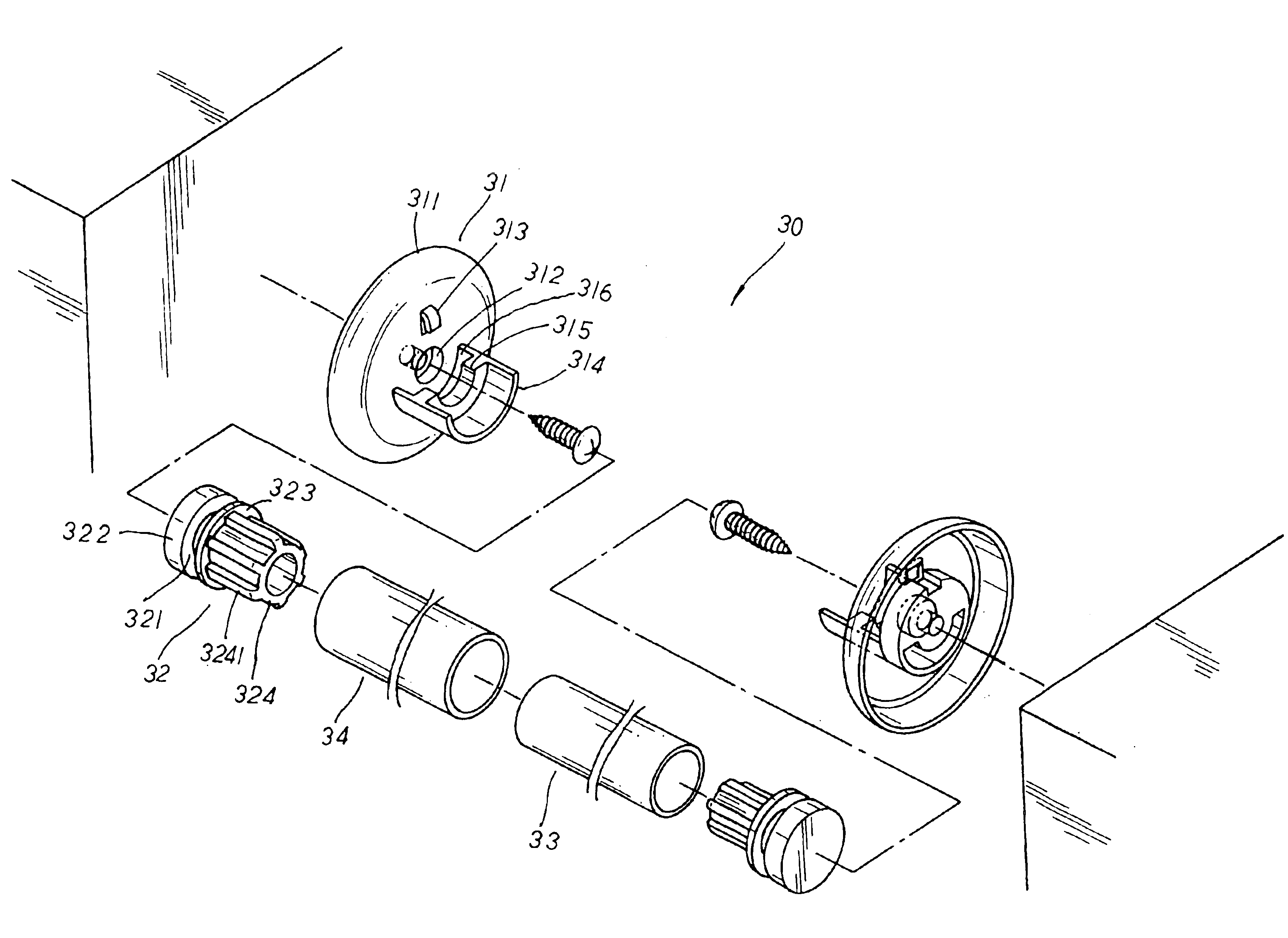
Please refer to FIG. 3. The present invention is related to a telescopic stick 30, including a retaining mount 31, a supporting sleeve 32, an inner tube 33, and an outer tube 34. The retaining mount 31 is made up of a base 311 disposed at one side thereof, a step-wise through hole 312 disposed at the center of the base 311 thereof, a resilient stop block 313 protruding at the upper surface of the base thereof, and a half-tubular abutment plate 314 extending outwards at the lower surface of the base thereof. The half-tubular abutment plate 314 has an arc registration rib 315 protruding properly at the inner side thereof, and an engagement groove 316 defined by the arc registration rib 315 and the base there-between. The supporting sleeve 32 has a circular registration recess 321 indented properly at one side thereof, an engagement ring 322 and an abutment face 323 of the same diameter protruding at both sides of the circular registration recess 321 thereof respectively, and a sleeve ...


PUM


Abstract

A telescopic stick includes a retaining mount, a supporting sleeve, an inner tube, and an outer tube wherein the retaining mount has a base disposed at one side thereof, a step-wise through hole disposed at the center of the base thereof, a resilient stop block protruding at the upper surface of the base thereof, and a half-tubular abutment plate extending outwards at the lower surface of the base thereof. The supporting sleeve has a circular registration recess defined by an engagement ring and an abutment face of the same diameter at both sides thereof respectively, and a sleeve column with axial flexible ribs distributed thereon to be adapted at the corresponding outer side of the inner and outer tubes therein respectively. In practical use, the inner and outer tubes in sleeve registration are adjusted of length in horizontal direction, and the supporting sleeve is attached to the retaining mount with the resilient stop block abutted tightly against the supporting sleeve for secure location thereon, preventing the inner and outer tubes from coming off there-from when pushed or pulled by outer force.

Description

BACKGROUND OF THE INVENTIONThe present invention is related to a telescopic stick, including a retaining mount, a supporting sleeve, an inner tube and an outer tube wherein the retaining mount has a base disposed at one side thereof, a step-wise through bole disposed at the center of the base thereof, a resilient stop block protruding at the upper surface of the base thereof, and a half-tubular abutment plate extending outwards at the lower surface of the base thereof. The supporting sleeve has a circular registration recess defined by an engagement ring and an abutment face of the same diameter at both sides thereof respectively, and a sleeve column with axial flexible ribs distributed thereon to be adapted at the inner and outer tubes therein respectively; whereby, the inner and outer tubes in sleeve engagement are adjusted of length in horizontal direction, and the supporting sleeve is securely located onto the retaining mount in assembly, preventing the inner and outer tubes fro...

Claims


Application Information

Patent Timeline
Patent Type & Authority Patents(United States)
IPC IPC(8): A47K3/38A47K3/28A47H1/102A47H1/00
CPCA47K3/38A47H1/102
Inventor HSU, BEN
Owner CHING FENG BLINDS INC CO LTD
Why Eureka
Try Eureka