
Flow-switching microdevice

a micro-fluidic device and flow-switching technology, which is applied in the direction of valve operating means/releasing devices, mechanical equipment, transportation and packaging, etc., can solve the problems of inability to adapt the valve structure that controls the flow of fluids in bulk to microfluidic devices, and the production of such devices presents various challenges. , to achieve the effect of improving the fluid flow control

Inactive Publication Date: 2005-01-25
AGILENT TECH INC
View PDF20 Cites 84 Cited by
  • Summary
  • Abstract
  • Description
  • Claims
  • Application Information

AI Technical Summary

Benefits of technology

Accordingly, it is an object of the present invention to overcome the above-mentioned disadvantages of the prior art by providing a microdevice that allows for improved fluid flow control.

Problems solved by technology

Nevertheless, the production of such devices presents various challenges.
This may involve forming motive force means such as electrodes, which may add to the cost of the microdevice.
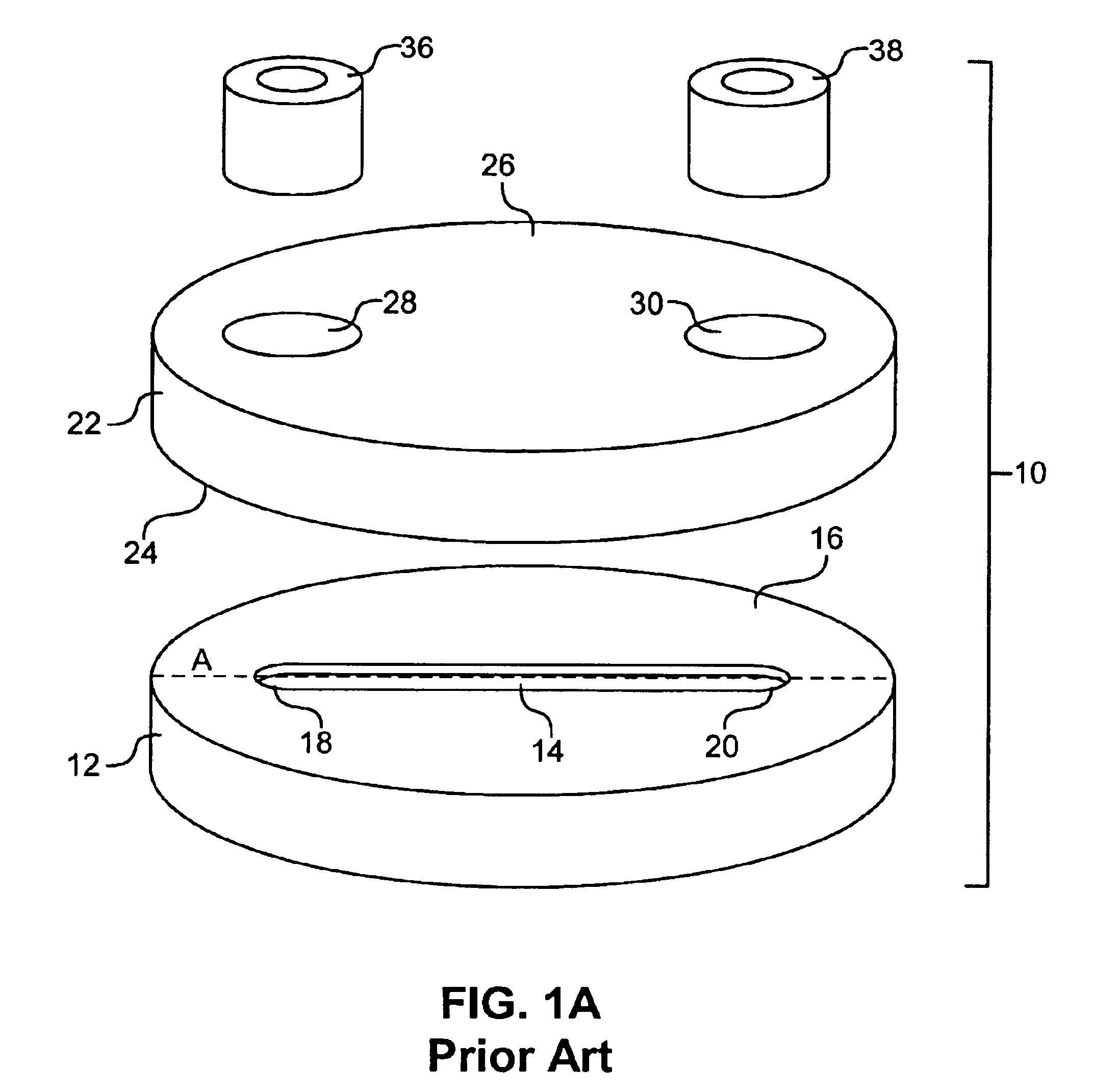
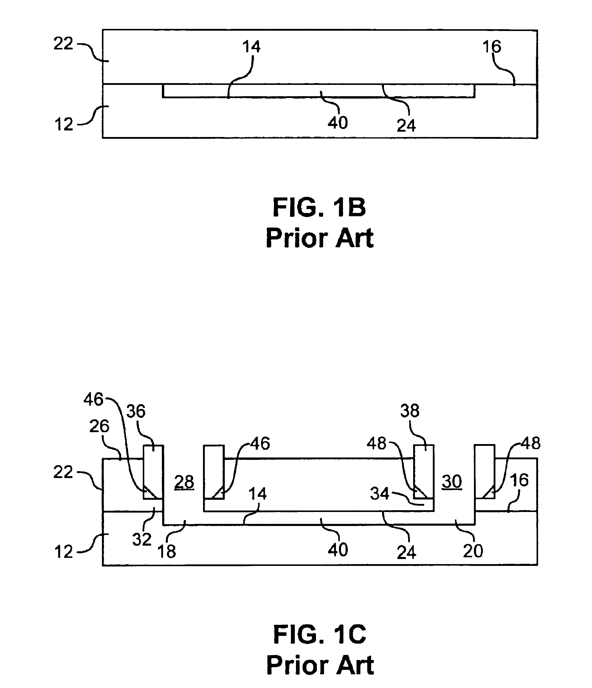
Since it is well known that the flow characteristics of fluids in the small flow channels of a microdevice differ greatly from flow characteristics of fluids in bulk, conventional wisdom dictates that valve structures that control flow of fluids in bulk are not easily adapted for use in microfluidic devices.
Many of these valves are complex in construction and are incapable of the fast response times required in certain biomolecule analysis applications due to an excess of “dead space,” i.e., unused and unnecessary space within the microdevice.

Method used


Image

  • Flow-switching microdevice
  • Flow-switching microdevice
  • Flow-switching microdevice

Examples


Embodiment Construction

Before the invention is described in detail, it is to be understood that unless otherwise indicated this invention is not limited to particular materials, components or manufacturing processes, as such may vary. It is also to be understood that the terminology used herein is for purposes of describing particular embodiments only, and is not intended to be limiting.

It must be noted that, as used in the specification and the appended claims, the singular forms “a,”“an” and “the” include plural referents unless the context clearly dictates otherwise. Thus, for example, reference to “a feature” includes a plurality of features, reference to “fluid” includes a mixture of fluids, and the like.

In this specification and in the claims that follow, reference will be made to a number of terms that shall be defined to have the following meanings, unless the context in which they are employed clearly indicates otherwise:

The term “controllable alignment” as used herein refers to the spatial relat...


PUM


Abstract

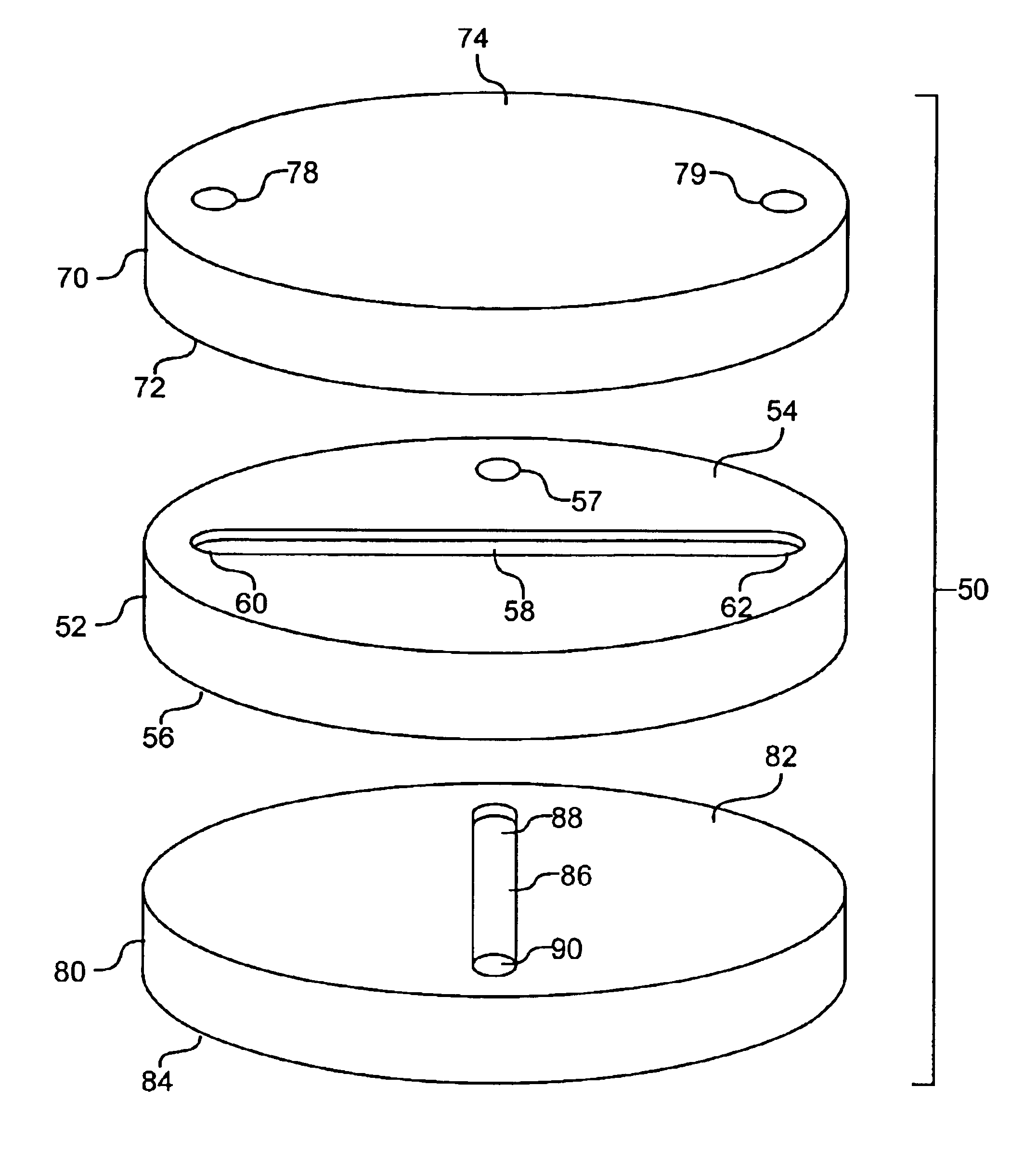
A microdevice is provided for controlling fluid flow. The microdevice includes a substantially planar contact surface and a plurality of fluid-transporting features associated therewith. Also included is a substrate having a substantially planar contact surface and a fluid-transporting feature associated therewith. The contact surfaces are positioned in slidable and fluid-tight contact to allow for controllable formation of a plurality of different flow paths upon alignment of the substrate fluid-transporting feature with each cover plate fluid-transporting features in succession. Typically, at least one of the cover plate and substrate is comprised of a biofouling resistant polymer, and the flow paths are of different lengths. Optionally, a plurality of fluid-transporting features is associated with the substrate so that flow paths are formed as a result of a different alignment of the fluid-transporting features.

Description

TECHNICAL FIELDThe present invention relates to fluid flow control in microdevices. More specifically, the invention relates to microdevices that employ a high-pressure-capable valve structure, the valve structure optionally achieving flow path switching through rotational or linear motion.BACKGROUNDMicrofluidic devices (microdevices) hold great promise for many applications, particularly in applications that employ rare or expensive fluids. Proteomics and genomics are two important areas in which microfluidic devices may be employed. For example, many of the best-selling drugs today either are proteins or act by targeting proteins. In addition, many molecular markers of disease, the basis of diagnostics, are peptidic or nucleotidic sequences. Thus, development effort to advance the diagnostics or pharmaceutical technologies has focused on the discovery of medically important proteins and the genes from which they derive. Thus, biomolecular identification is a particularly important...

Claims


Application Information

Patent Timeline
IPC IPC(8): F15C5/00F16K99/00
CPCF15C5/00F16K99/0001F16K99/0011F16K99/0013F16K2099/0084F16K2099/0076F16K2099/0078F16K2099/008F16K2099/0074Y10T137/86863
Inventor KILLEEN, KEVINYIN, HONGFENG
Owner AGILENT TECH INC
Learn More