On chip control of fluids using electrodes

a technology of fluid control and electrodes, applied in electrolysis components, positive displacement liquid engines, laboratory apparatus, etc., can solve the problems of reducing the amount of sample fluid that is possible to handle, affecting the reproducibility of diagnostic microfluidic-based tests, and reducing the speed of the fluid flow front with the distance travelled, so as to improve the ability of stopping, increase the hydrophobicity of the surface, and increase the hydrophobicity of the reference electrode

Inactive Publication Date: 2015-07-23
GINOLIS
View PDF3 Cites 12 Cited by
  • Summary
  • Abstract
  • Description
  • Claims
  • Application Information

AI Technical Summary

Benefits of technology

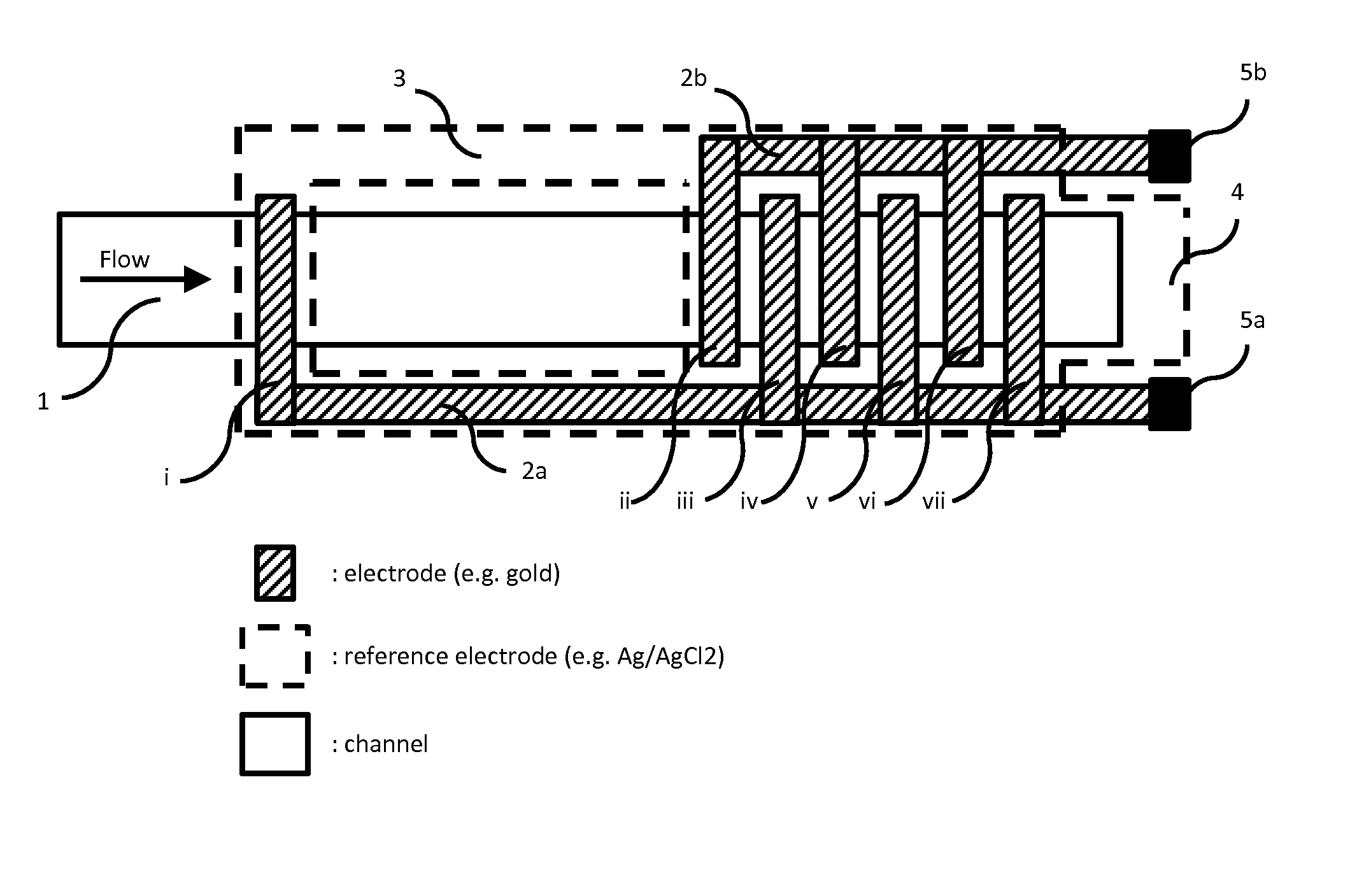
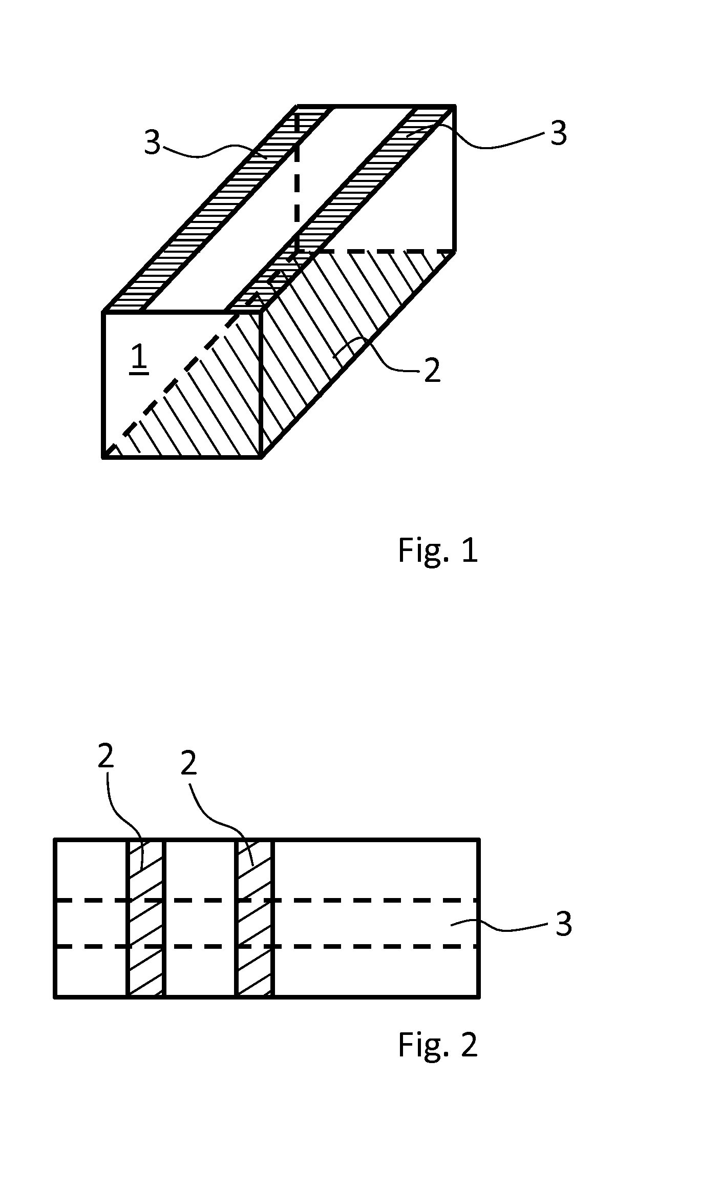
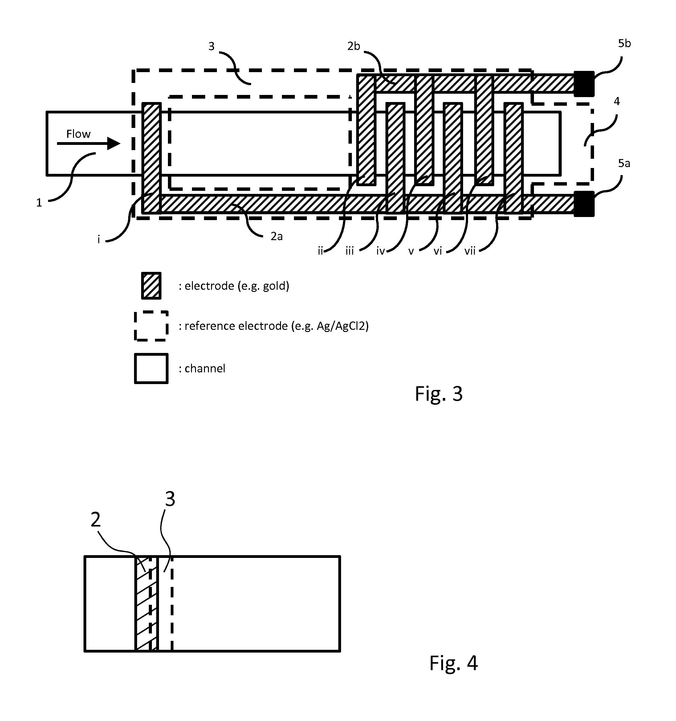
[0056]According to an embodiment of the present invention, the working electrode and / or the reference electrode may comprise a structured surface adapted to contact the fluid sample during use of the device. The structured surface may for example be a micro- and / or nanostructured surface (e.g. ridges, pillars, etc.). This embodiment is advantageous in that the structured surface may increase the hydrophobicity of the surface of the working electrode in its inactivated state (i.e. with no voltage applied). It may also increase the hydrophobicity of the reference electrode. Since the fluid front may tend to stop propagating as it encounters a hydrophobic surface, this embodiment may enable an improved ability of stopping, and thereby controlling, the fluid flow.
[0057]According to an embodiment of the present invention, the device may comprise at least one hydrophobic surface portion arranged to contact the fluid sample as it moves along the flow path, and wherein at least a portion of said hydrophobic surface portion is arranged abreast of at least a portion of the working electrode. Thereby the hydrophobic surface portion may cooperate with a working electrode such that the fluid sample, in case the working electrode e.g. is in a hydrophobic state, may be prevented from passing the hydrophobic surface portion and hence the control of the fluid flow may be improved. The hydrophobic surface portion may have a water contact angle (WCA) exceeding 80 degrees, such as exceeding 100 degrees WCA, and preferably exceeding 120 degrees WCA.The hydrophobic surface properties of the hydrophobic surface portion may depend on surface chemistry (e.g. fluorinated materials) or on pinning effects of micro / nano structures (e.g. ridges, pillars, etc.) or on a combination thereof. Pinning effect may as an example be understood as the fluid arresting effect occurring when the fluid is to pass a sharp edge, such as a micro- and / or nano-structured ridge or groove. It will however be appreciated that other suitable materials, effects or structures may be used for preventing the fluid sample from passing the portion of the working electrode and thereby provide a flow gate or stop in the channel.

Problems solved by technology

However, for diagnostic applications the variable composition and viscosity of biological samples puts up a major challenge to microfluidic assay development.
These variations, along with variations in the surface properties of the microfluidic chips, causes variations in timing, volumes and flow rates and can thereby negatively affect the reproducibility of diagnostic microfluidic-based tests.
However, a major drawback with the electrochemical electrowetting microfluidics technology according to prior art is that the speed of the fluid flow front may rapidly decrease with the distance travelled along the flow path.
However, a channel length limitation of about 1 cm is for practical reasons limiting the amount of sample fluid that is possible to handle (in terms of timing, volumes and flow rates), to nanoliter volumes rather than microliter volumes.
When targeting applications within medical diagnostics this is a major drawback, since most point of care tests require a sample volume in the microliter range in order to produce accurate and reproducible results.
The channel length limitation is for practical reasons also limiting the number of working electrodes that are possible to place along the flow path, given a certain minimal working electrode size possible to produce cost effectively (for instance the smallest working electrode possible to produce with a metal sputter mask instead of photolithography).
However, a limited number of fairly large working electrodes, relative to the length of the channel, is thus limiting the number of operations and the possibility of fine-tuned flow control.
Altogether, due to a channel length limitation of about 1 cm or even less, prior art has a limited ability to handle microliter volumes of sample fluid with the firm control of timing, volumes and flow rates required for many applications within medical diagnostics.
The switching of the applied voltage may also include a time delay, such as a predetermined “idle time” during which the applied voltage is zero, or close to zero.

Method used


Image

  • On chip control of fluids using electrodes
  • On chip control of fluids using electrodes
  • On chip control of fluids using electrodes

Examples


example 1

[0098]The experiment described herein was done to determine the influence of reference electrode 3 placement on fluid flow length. In-house produced microfluidic chips were used for fluid flow tests to characterize electrowetting actuated fluid flow rate and length. Microfluidic chips were constructed by assembly of the following: a gold coated microscopic slide 2, a 73 μm self-adhesive spacer tape 8, a cyclo olefin polymer (COP) plastic film 9 as is, or with a screen printed silver / silver chloride reference electrode 3 facing the microchannel 1.

[0099]FIG. 6 shows the composition of the different layers of the microfluidic chips where the gold coated slide 2 make up the floor, the spacer tape 8 the walls, and the COP film 9 (including the reference electrode 3) the roof of the microfluidic channel 1. Thus, the microfluidic channel 1 or flow path 1 is here defined by a plane metallic electrode at the bottom, spacer tape 8 walls of the spacer tape 8 at the sides, and reference electro...

example 2

[0109]The experiment described herein was done to further examine and characterise the influence of reference electrode 3 placement on electrowetting actuated fluid flow rate and flow length.

[0110]Microfluidic chips were constructed by assembly of the following:

[0111]i) Cyclo-olefin polymer (COP) plastic film 9:[0112]a. 188 μm thick[0113]i. sputter coated with titanium and gold (50 Å titanium and 1000 Å gold)[0114]b. 100 μm thick[0115]i. as is[0116]ii. with a screen printed silver / silver chloride reference electrode 3 facing the microchannel 1

[0117]ii) 73 μm self-adhesive spacer tape 8.

[0118]Chip layers were assembled as described in Example 1. 20 μl bovine serum was used as fluid sample and was applied to the sample loading hole 10 of each chip using a micropipette. The fluid sample was allowed to settle in the sample loading hole for 30 seconds, to allow it to wet the COP film 9 edges bordering the loading hole 10, where after minus (−) 1.2 V was applied to the working electrode 2...


PUM

PropertyMeasurementUnit
voltageaaaaaaaaaa
voltageaaaaaaaaaa
lengthaaaaaaaaaa

Abstract

The present invention relates to a device for controlling movement of a fluid sample along a flow path and a corresponding method. The device comprises a working electrode (2) arranged to contact the fluid sample when the fluid sample moves along the flow path, and a reference electrode (3) arranged to contact the fluid sample when the fluid sample moves along the flow path. At least a portion of the reference electrode is arranged abreast of or downstream at least a portion of the working electrode. The present invention is advantageous in that it provides a device wherein a fluid sample may be transported and accurately controlled, with respect to e.g. timing, volumes and flow rates, over greater distances compared to prior art.

Description

TECHNICAL FIELD [0001]The present invention relates to devices for controlling movement of fluid samples in microfluidic chips and to a method for controlling or manipulating a fluid flow through channels of such microfluidic chips. The microfluidic chips may be used in biotechnological, diagnostical and pharmaceutical applications.BACKGROUND OF THE INVENTION[0002]Microfluidics relates to a multidisciplinary field comprising physics, chemistry, engineering and biotechnology that studies the behavior and flow of fluids at nano and microliter scale inside open or closed microchannels. Microfluidics has enabled the development of so-called ‘lab-on-a-chip’ devices and systems that can process microliter and nanoliter volumes of sample fluid, and perform highly complex and sensitive analytical measurements. ‘Lab-on-a-chip’ indicates the scaling of single or multiple laboratory processes down to a chip-format, which is only millimeters to a few centimeters in size.[0003]Microfluidic-based...

Claims


Application Information

Patent Timeline
Patent Type & Authority Applications(United States)
IPC IPC(8): G01N27/447
CPCG01N27/44791B01L3/50273B01L3/502784B01L2300/0887B01L2400/0427F04B19/006F04B43/043
Inventor JANSSON, FREDRIKMOLIN, MAGNUS
Owner GINOLIS
Why Eureka
Try Eureka