Airbag inflator diffuser system and method of manufacture

a diffuser and airbag technology, applied in the direction of pedestrian/occupant safety arrangement, vehicle components, vehicular safety arrangments, etc., can solve the problems of improper inflator of curtain airbags, occupants being thrown against windows, doors and side walls of vehicles, etc., to achieve effective diffuser and cool gas, simple fabrication and installation, and minimal cost

Inactive Publication Date: 2005-01-25
AUTOLIV ASP INC
View PDF20 Cites 45 Cited by
  • Summary
  • Abstract
  • Description
  • Claims
  • Application Information

AI Technical Summary

Benefits of technology

The apparatus of the present invention has been developed in response to the present state of the art, and in particular, in response to the problems and needs in the art that have not yet been fully solved by currently available airbag inflator diffusion systems. Thus, the present invention provides an airbag inflator diffusion system which is simple to fabricate and install, is compact, directs gas exiting the inflator, effectively diffuses and cools the gas, and may be fabricated with minimal expense.

Problems solved by technology

If the airbag cover freely moves into the passenger compartment, it may injure a passenger.
In these accidents, the occupant may be thrown against the windows, doors and side-walls of the vehicle.
The holes may cause the curtain airbag to inflate improperly.
These exhaust passages occupy valuable space when the diffuser and inflator are installed and not in use.
Generally, doing so adds to the production and design costs of the inflator.
Such securement techniques generally increase production time and assembly costs.
Additionally, non-standard inflator / diffuser combinations may increase training time required for workers assembling the airbag apparatus.
Custom fabrication is also expensive.
This adjustment adds delay and a skill requirement in the assembly process of the completed airbag apparatus.

Method used


Image

  • Airbag inflator diffuser system and method of manufacture
  • Airbag inflator diffuser system and method of manufacture
  • Airbag inflator diffuser system and method of manufacture

Examples


Embodiment Construction

The present invention can be better understood with reference to the drawings where like parts are designated with like numerals throughout.

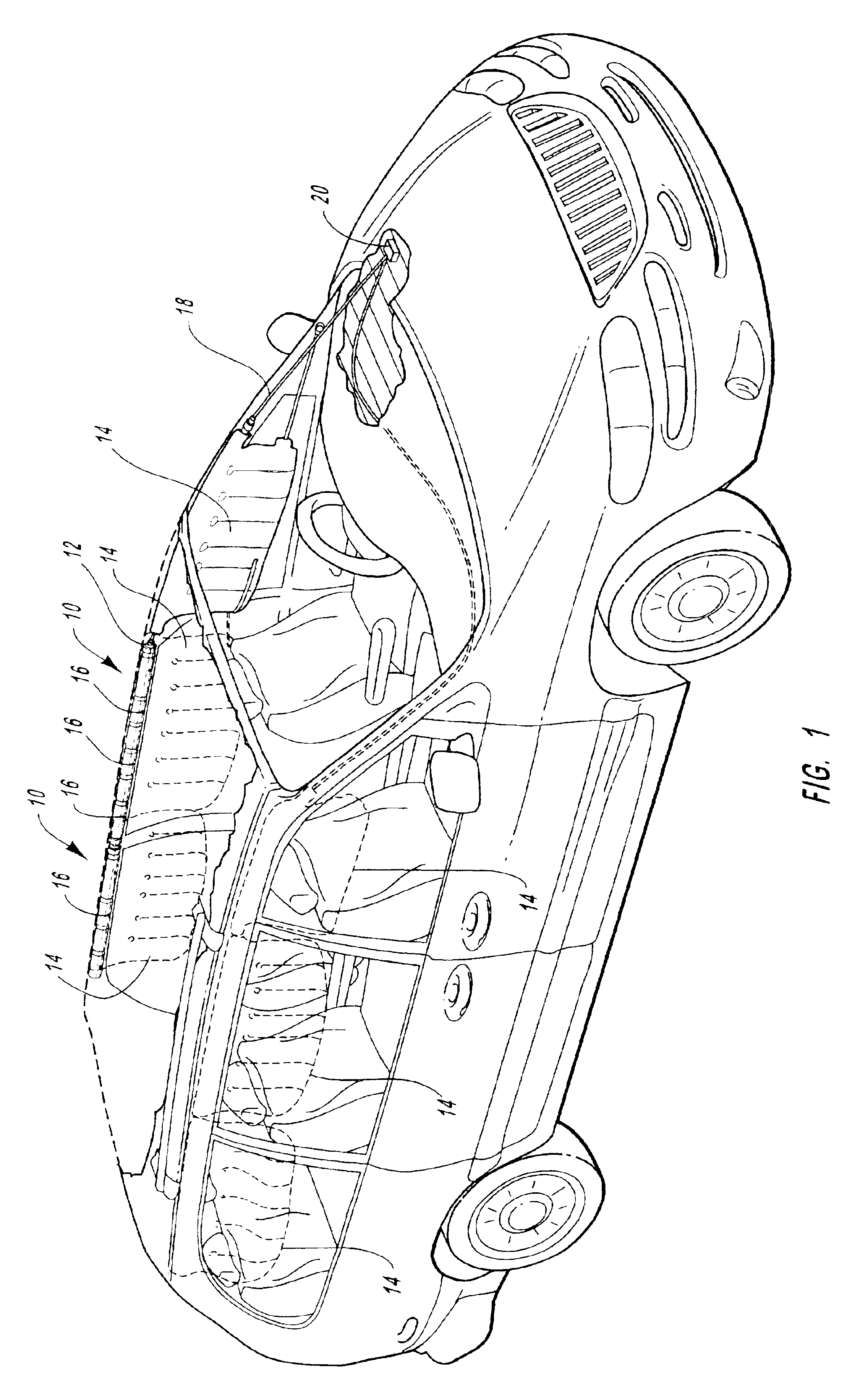
FIG. 1 is a perspective view illustrating where curtain airbag apparatuses 10 are generally installed. FIG. 1 illustrates a conventional vehicle equipped with a plurality of curtain airbag apparatuses 10. The illustrated vehicle is a van with large windows and sides. The windows are larger than those generally found in passenger cars. The larger windows increases the need for curtain airbag apparatuses 10. The van has door and window frames which connect the body of the vehicle to the vehicle roof. The vehicle roof includes a roof frame.

FIG. 1 also illustrates how the curtain airbag 14 deploys along an interior side of a vehicle. A curtain airbag inflation apparatus 10 is generally mounted behind an airbag cover (not shown) to the vehicle roof frame between a side door / window and the vehicle roof. Vehicles are generally designed to minimize the ...


PUM


Abstract

An airbag inflator system and method of manufacture is disclosed which may be stored in a small area, is simple to fabricate, directs exhaust gas from a standardized inflator, sufficiently cools and diffuses the exhaust gas, and catches hot gas generant residue. The system includes an airbag inflator within a sleeve. Solid sections of the sleeve circumscribe the inflator and are positioned to divert exhaust gas leaving an exit port of the inflator. The configuration of the solid sections provides that the inflator need not be rotated during assembly to position exit ports below solid sections. The diverted exhaust gas unrolls the sleeve to form an exhaust passage. The gas passes through the exhaust passage and is dispersed by the permeable section before entering the textile airbag. In this way, a simple, effective diffusion system for curtain airbag inflators is provided.

Description

BACKGROUND OF THE INVENTION1. The Field of the InventionThe present invention relates to airbag inflation systems in motor vehicles. More specifically, the invention relates to an airbag diffusion system for diffusing inflation gases exiting a curtain airbag inflator.2. Technical BackgroundInflatable airbags are well accepted for use in motor vehicles and have been credited with preventing numerous deaths and injuries. Some statistics estimate that frontal airbags reduce the fatalities in head-on collisions by 25% among drivers using seat belts and by more than 30% among unbelted drivers. Statistics further suggest that with a combination of seat belt and airbag, serious chest injuries in frontal collisions can be reduced by 65% and serious head injuries by up to 75%. Airbag use presents clear benefits and vehicle owners are frequently willing to pay the added expense for airbags.A modern airbag apparatus may include an electronic control unit (ECU) and one or more airbag modules. T...

Claims


Application Information

Patent Timeline
Patent Type & Authority Patents(United States)
IPC IPC(8): B60R21/26B60R21/261
CPCB60R21/26B60R2021/2617
Inventor SMITH, BRADLEY W.
Owner AUTOLIV ASP INC
Why Eureka
Try Eureka