Reverse taper cutting tip with a collar

a cutting tip and taper technology, applied in cutting machines, cutting machines, manufacturing tools, etc., can solve the problems of reducing the efficiency of the machine, reducing affecting the service life of the machine, so as to reduce the potential for breakage and prolong the useful life of the tool

Inactive Publication Date: 2005-01-25
THE SOLLAMI COMPANY
View PDF3 Cites 93 Cited by
  • Summary
  • Abstract
  • Description
  • Claims
  • Application Information

AI Technical Summary

Benefits of technology

In the preferred embodiment the collar is made of softer grade of tungsten carbide than the central portion thereof such that the collar will assist in retaining the central portion to the forward end of the tool and will absorb some of the shock incurred to the head of the tool as it cuts hard surfaces and thereby reduce the potential for breakage of the tungsten carbide insert from the tool body. The relatively large diameter of the insert, including the outer diameter of the collar, provides protection to the forward end of the body of the tool thereby extending the useful life of the tool.

Problems solved by technology

The tools suffer wear as a result of being moved against the hard material being cut and have to be replaced at regular intervals.
Each time the tools are replaced, the machine is taken out of service for a lengthy period of time.
The frequency with which tools have to be replaced and the time consumed during the replacement process therefore reduce the efficiency of the machine and increase the cost of its operation.
The energy needed to operate the machines, and therefor the cost of operation, increases if the cutting tips become too blunt before the tool body has become sufficiently worn to require replacement.
Tool failure can occur as a result of the failure the braze material holding the tungsten carbide tip into the seat at the forward end of the tool body.
Theoretically, the life of the cutting insert will be increased by providing a larger sized insert, however enlarging all diameters of a currently available one piece tungsten carbide cutting tip will reduce the efficiency of the machine because the tip will rapidly become blunt.
Since the tungsten carbide is the most expensive element in the tool, increasing the size of the insert will also increase tool cost.
On the other hand, the metal which makes up the tool bodies is subject to wash away causing the tool to fail as aggregate of the hard material cut by the machine erodes away the metal of the tool body behind the tungsten carbide tip.
Efforts to make a tool having a harder insert, however, have not been successful partly because harder grades of tungsten carbide are more brittle and tend to fracture, and partly because the harder grades of tungsten carbide are more difficult to manufacture.
If the particles are not uniformly compacted the completed insert will have less dense areas, or porosity, and be subject to failure.
One difficulty with the Sollami insert has been the difficulty of properly assembling the parts of the insert and maintaining the part in their correct relationship during the brazing process.
Specifically, the weight of the tungsten carbide collar is insufficient to push the collar through the liquefied braze material until it seats properly at the bottom of the seat.

Method used


Image

  • Reverse taper cutting tip with a collar
  • Reverse taper cutting tip with a collar

Examples


Embodiment Construction

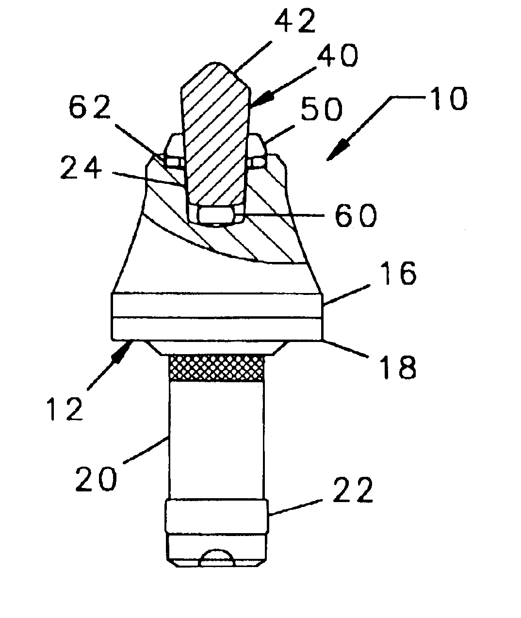
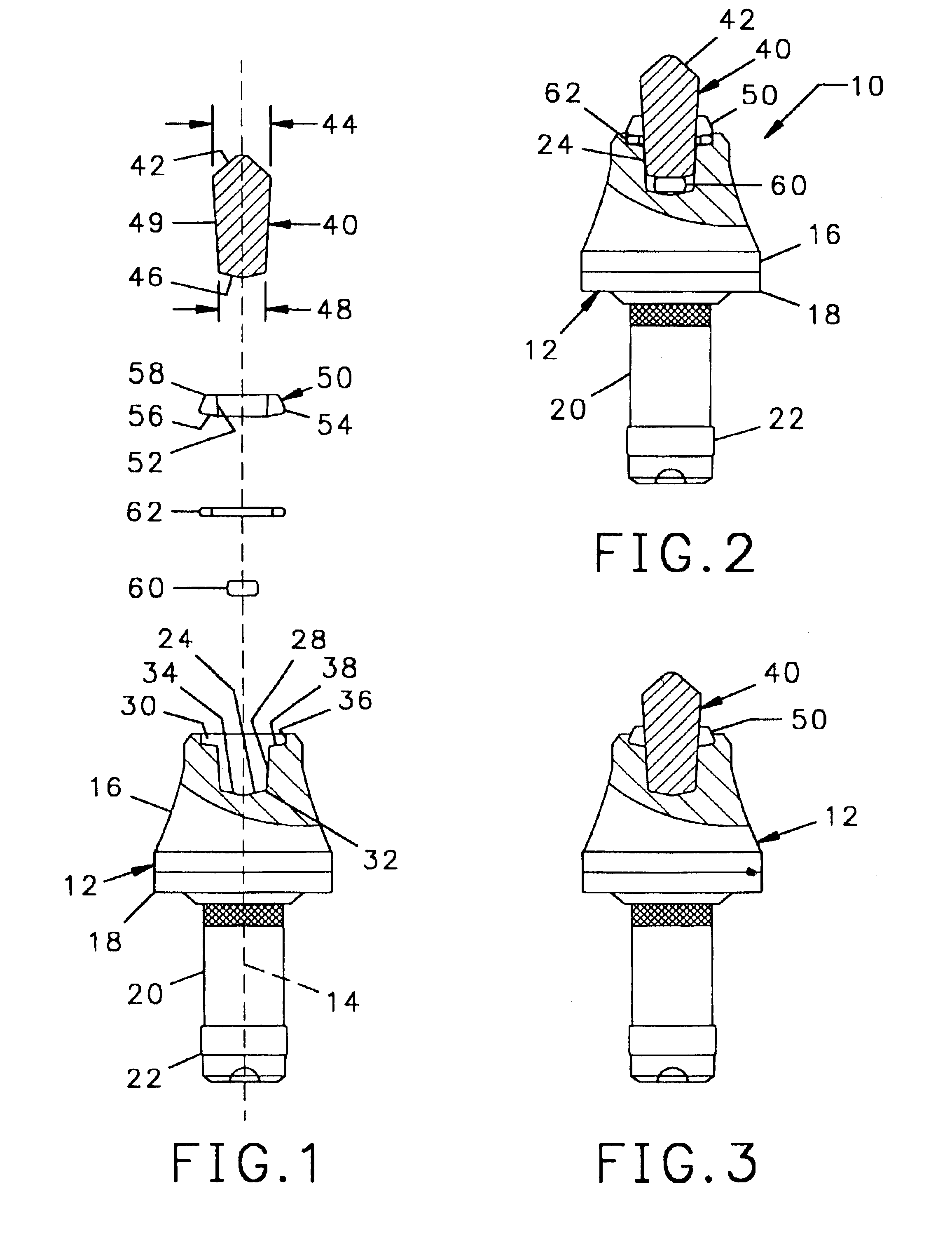
Referring to FIGS. 1, 2 and 3, a tool 10 has an elongated body 12 symmetrical about its longitudinal axis 14. The tool includes a tapered forward section 16, at the rearward end of which is a radial flange 18. Extending axially rearward of the flange 18 is a cylindrical shank 20 at the distal end of which is a cylindrical hub 22. At the forward end of the forward section 16 is a seat 24 into which is brazed a cutting insert 26.

In accordance with the invention the seat 24 has a frustoconical central portion 28 with a large diameter forward end 30 and a smaller diameter lower end 32. At the bottom of the central portion 28 is a conical floor 34. Extending around the large diameter forward end 30 is a countersink portion consisting of a cylindrical inner wall 36 having a diameter considerably larger than that of the large diameter forward end 30, and a generally planer annular shoulder 38 between the rearward end of the cylindrical wall 36 and the large diameter forward end 30 of the f...


PUM

PropertyMeasurementUnit
base diameteraaaaaaaaaa
outer diameteraaaaaaaaaa
diameteraaaaaaaaaa

Abstract

A cutting tool has tool body with a seat at a forward end thereof. A hard cutting insert is bonded into the seat. The insert is made of a hard material and Ahas an elongate central portion having a maximum upper diameter and a maximum lower diameter that is less than the maximum upper diameter. A collar, also made of a hard material, surrounds the base of the elongate central portion of the insert.

Description

BACKGROUND OF THE INVENTIONMachines used to break up concrete and asphalt pavement and other hard surfaces have a plurality of tools mounted on a cutting wheel which is forced against the surface to be broken. Each tool has an elongate steel body at the forward end of which is a tungsten carbide cutting tip. When the wheel rotates, the tools are carried through a circular orbit and the tungsten carbide tips penetrate the hard surface with each tip removing a small amount of material, thereby advancing the cut.The tools suffer wear as a result of being moved against the hard material being cut and have to be replaced at regular intervals. Each time the tools are replaced, the machine is taken out of service for a lengthy period of time. Machines used to break up concrete and asphalt roadways are kept in continuous operation through the work day except for when the tools are being replaced, and it is not uncommon to replace the tools in such machines two or three times during a work d...

Claims


Application Information

Patent Timeline
Patent Type & Authority Patents(United States)
IPC IPC(8): B28D1/18
CPCB28D1/188E21C35/18
Inventor SOLLAMI, PHILLIP A.
Owner THE SOLLAMI COMPANY
Why Eureka
Try Eureka