Gripper device

a technology of gripper and spherical plate, which is applied in the field of gripper devices, can solve the problems of unnecessary use of expensive and cumbersome gearing, and achieve the effect of avoiding unnecessary energy loss and undesirable heating up

Inactive Publication Date: 2005-01-25
HUGH STEEPER
View PDF12 Cites 13 Cited by
  • Summary
  • Abstract
  • Description
  • Claims
  • Application Information

AI Technical Summary

Benefits of technology

To avoid unnecessary loss of energy and undesirable heating up of the component parts of the gripper, it is desirable for the control means to be connected to the end-of-movement detector means and to be so constructed and connected that the control means stop the supply of electrical current from both th

Problems solved by technology

A disadvantage in such a construction is that, in order to increase the strength of the gripping action once the two por

Method used


Image

  • Gripper device
  • Gripper device
  • Gripper device

Examples


Embodiment Construction

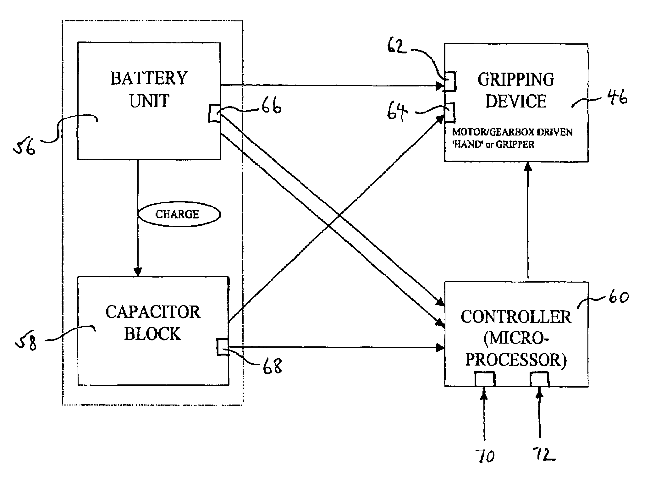
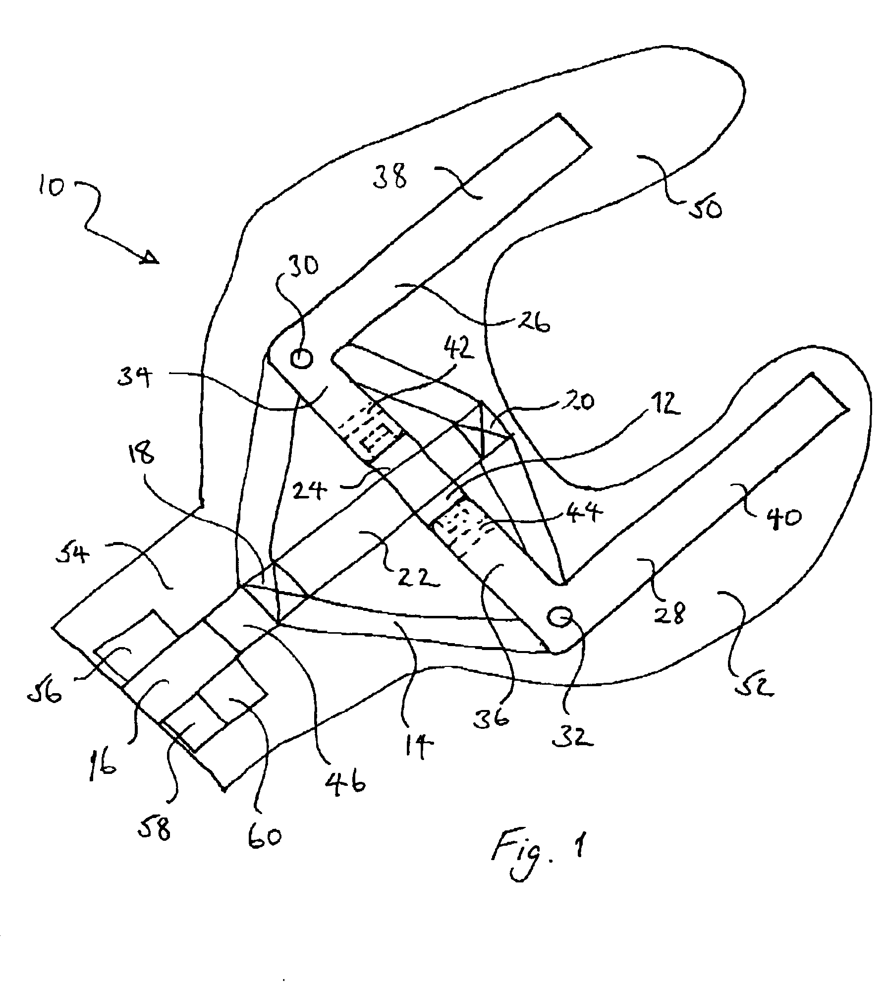
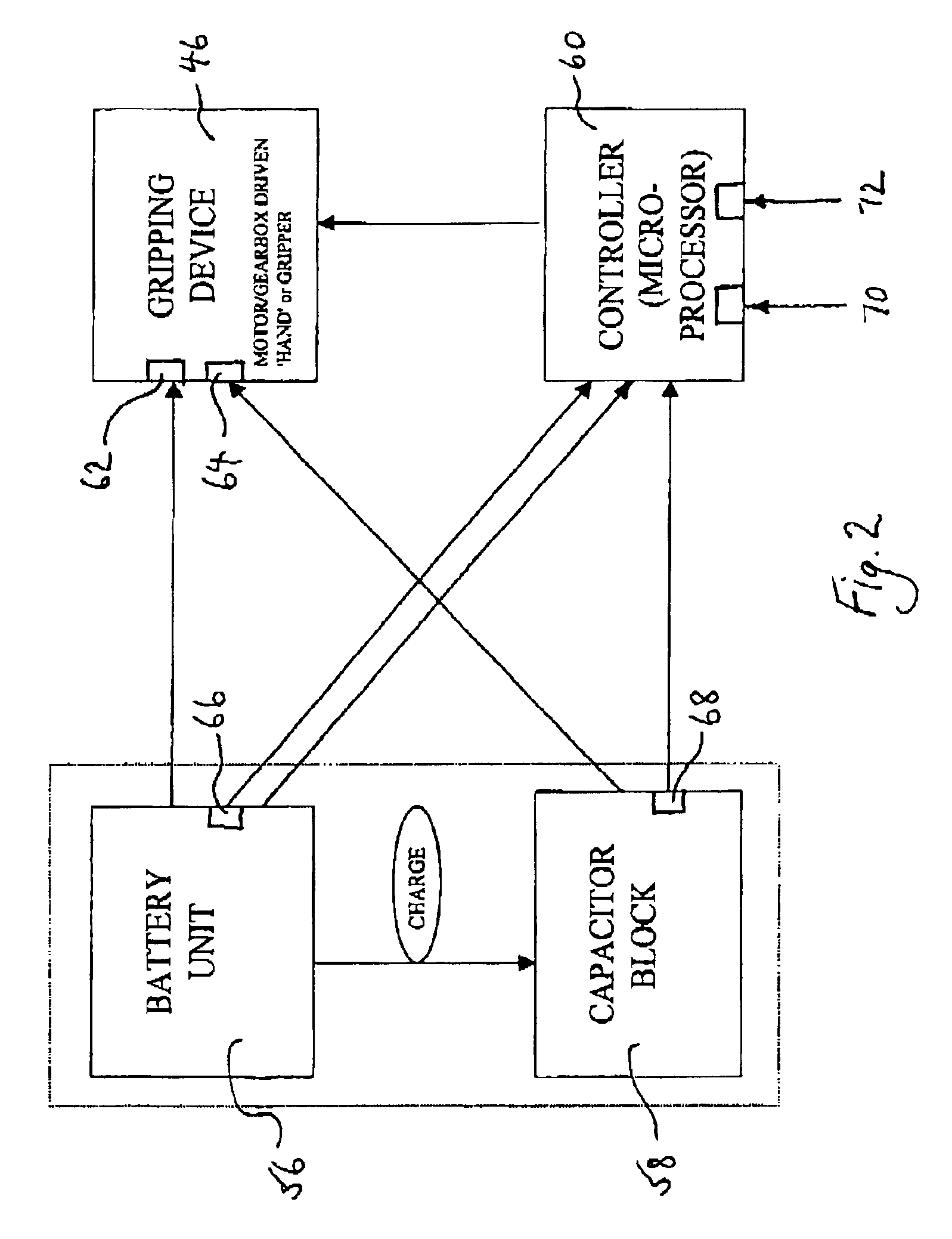
FIG. 1 shows a hand prosthesis 10 in which is incorporated a gripper device 12. The gripper device 12 comprises a mounting frame or plate 14 secured rigidly to one end of a shaft 16. Two rotary bearings 18 and 20 are fixed to the frame 14 spaced apart along an axis which is co-linear with the shaft 16. A screw threaded rod 22 extends between the bearings 18 and 20 so as to be rotatable about that axis.

A nut 24 is threaded on this screw 22. Two L-shaped members 26 and 28 are pivotably connected at their corners to the frame 14 at pivots 30 and 32 respectively, such that respective limbs 34 and 36 are slidably secured to the nut 24 whilst the other limbs 38 and 40, respectively, of the L-shaped members 26 and 28 extend generally parallel to one another away from the shaft 16.

Slots 42 and 44 are formed in the L-shaped members 26 and 28 where they are slidably attached to the nut 24 to facilitate such sliding whilst inhibiting rotation of the nut.

A motor 46 is secured to the shaft 16 in...


PUM


Abstract

A gripper device comprising at least two portions which are coupled together and which can be moved towards one another to effect a gripping action and away from one another to effect a release action. An electrical motor is arranged to effect such movement, and a battery is connected to supply electrical current to the motor. A capacitor device is also connected to be capable of supplying electrical current to the electrical motor. A control device is arranged to cause the capacitor device to supply electrical current to the electrical motor after supply of electrical current to the electrical motor by the battery, to increase the strength of the gripping action.

Description

TECHNICAL FIELDThe present invention relates to a gripper device comprising at least two portions which are coupled together and which can be moved towards one another to effect a gripping action and away from one another to effect a release action, an electrical motor arranged to effect such movement, and a battery connected to supply electrical current to the motor.BACKGROUND ARTSuch a gripper device has been used in a band prosthesis which the user can operate to grasp objects. A disadvantage in such a construction is that, in order to increase the strength of the gripping action once the two portions come into contact with the article which is being grasped, it is necessary to use expensive and cumbersome gearing.SUMMARY OF THE INVENTIONThe present invention seeks to obviate this drawback.Accordingly, the present invention is directed to a gripper device having the construction set out in the opening paragraph of the present specification, further comprising capacitor means also...

Claims


Application Information

Patent Timeline
IPC IPC(8): A61F2/50A61F2/58B25J19/00B25J9/16B25J15/02A61F2/70A61F2/76
CPCA61F2/58B25J19/005B25J9/1612B25J15/0206A61F2/588A61F2002/507A61F2002/587A61F2002/7635A61F2002/704
Inventor SENOIR, MARTIN
Owner HUGH STEEPER
Why Eureka
Try Eureka