Multilayer coaxial structures and resonator formed therefrom

Inactive Publication Date: 2005-01-25
NOKIA CORP
View PDF11 Cites 83 Cited by
  • Summary
  • Abstract
  • Description
  • Claims
  • Application Information

AI Technical Summary

Problems solved by technology

This creates a potential reliability risk due to the increased number of joints, additional electrical loss, and increased temperature related to discontinuity effects.
Manufacturing is expensive because of the discrete nature of a coaxial line.
Due to the effect of radiation, especially at high freque

Method used


Image

  • Multilayer coaxial structures and resonator formed therefrom
  • Multilayer coaxial structures and resonator formed therefrom
  • Multilayer coaxial structures and resonator formed therefrom

Examples


Embodiment Construction

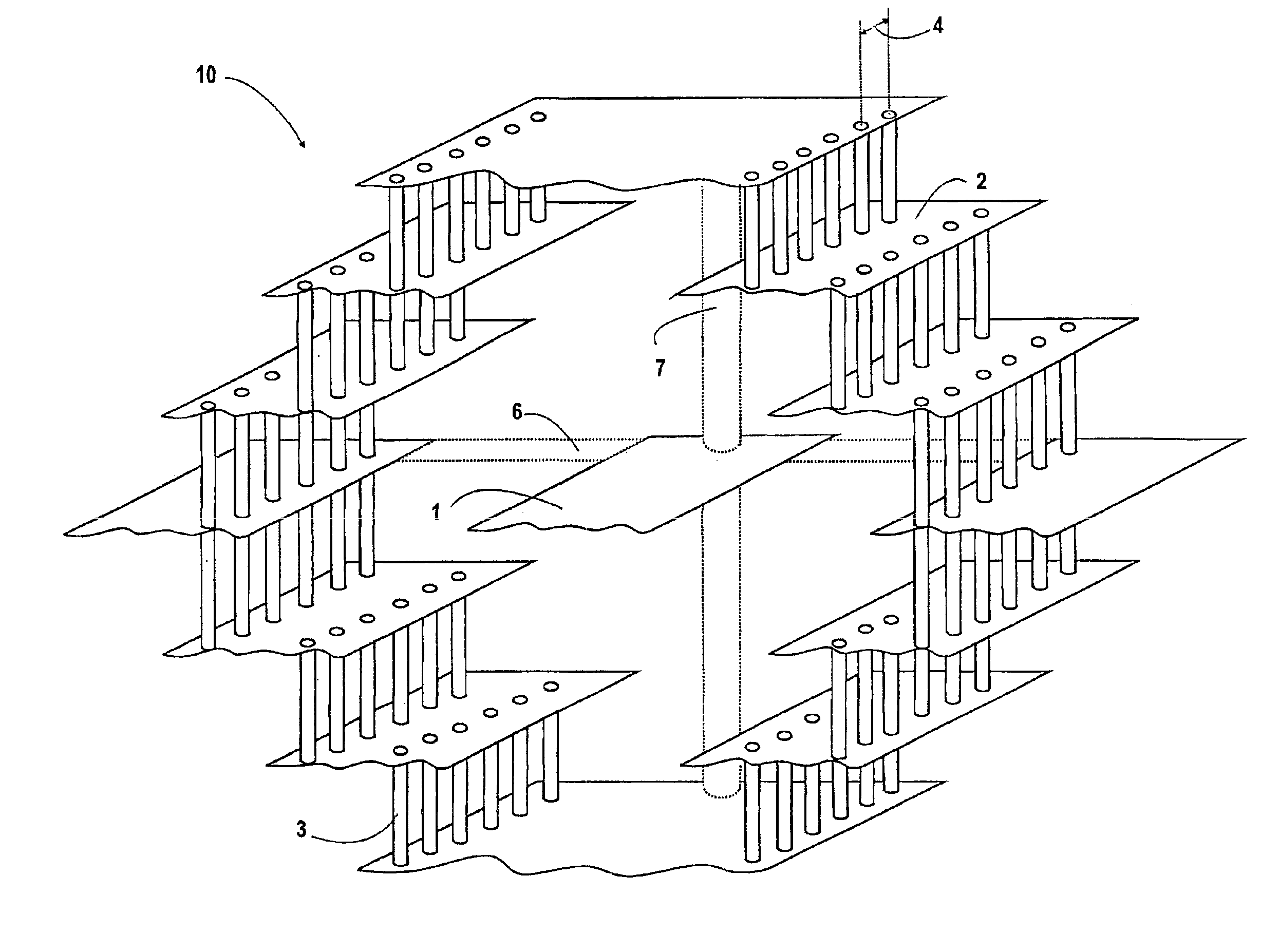
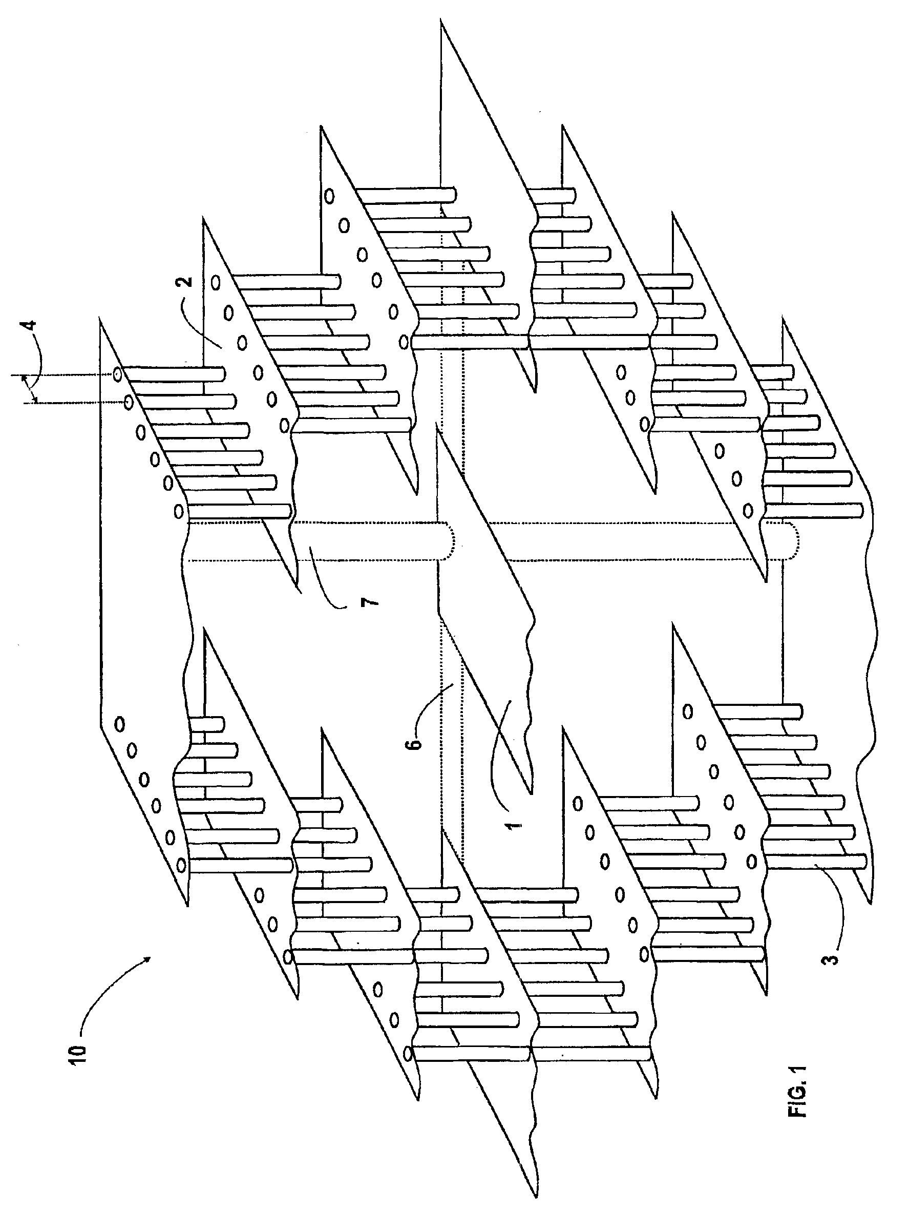
FIG. 1 depicts an example of the coaxial structure (10) according to the invention. The innermost line strip (1) of the multilayer structure forms a transmission line for a signal, and the outermost line strips (2) in different layers of a circuit board, which are connected by via posts (3) to each other, form a ground conductor. The outermost line strips are arranged to form as round a circle as possible in order to imitate the actual coaxial waveguide. The distance (4) between the via posts should be less than a quarter in wavelength in order to guarantee good isolation between the coaxial structure and the rest of the circuit board. The via post separation (4) must not be more than half a wavelength, since otherwise multiple transmission lines start to behave like coupled resonators, resulting in severe oscillations within the structure. The minimum length between via posts is determined by the mechanical strength of a circuit board structure.

In multilayer ceramics technology, it...


PUM


Abstract

The idea of the invention is to fabricate a multilayer coaxial transmission line into a printed circuit. The outermost conductor is fabricated by conductive conduit strips in different layers, using conductive via posts in isolation layers connecting the strips. The innermost conductor can be a single conductive strip or multiple strips in different layers connected together through conductive via posts.

Description

FIELD OF THE INVENTIONThis invention relates to waveguides, transmission lines, and resonators in multilayer printed circuit board structures. In particular the invention concerns a coaxial line structure in printed circuits.BACKGROUND OF THE INVENTIONPrior art transmission lines used in printed circuits have mainly been microstrips, coplanar waveguides, and striplines. If a coaxial line would have been needed in a circuit board, the coaxial line would have been attached separately to the surrounding circuitry on the surface of the printed circuit. This creates a potential reliability risk due to the increased number of joints, additional electrical loss, and increased temperature related to discontinuity effects. Manufacturing is expensive because of the discrete nature of a coaxial line. Coaxial structures are also relatively large because the dielectric material in the coaxial has a low dielectric constant (;=2-4). Conventional coaxial structures also need space for supporting an...

Claims


Application Information

Patent Timeline
IPC IPC(8): H01P3/02H01P3/06H05K1/02H05K1/00
CPCH01P3/06H05K1/0219H05K2201/09845H05K1/0298H05K2201/09618H05K1/0237
Inventor SALMELA, OLLIKOKKONEN, ILPO
Owner NOKIA CORP
Why Eureka
Try Eureka