Planar coil and planar transformer

Inactive Publication Date: 2005-01-25
TDK CORPARATION
View PDF15 Cites 29 Cited by
  • Summary
  • Abstract
  • Description
  • Claims
  • Application Information

AI Technical Summary

Benefits of technology

It is a first object of the invention to provide a planar coil and a planar tra

Problems solved by technology

In contrast to this, it is difficult to reduce the size of magnetic components such as choke coils and transformers, the other major components of the switching power supply.
This, however, present a problem that the copper loss that is a loss in the conductor increases due to the skin effect.
However, in this case, resistance becomes higher at the outer portions of the winding, which consequently causes an increase in the resistance of the entire winding.
However, the aforementioned methods have the following problems.
Thus, it is difficult for the first method to make the planar coils or planar transformers smaller in thickness.
In the second method, conductor layers as many as the number of turns required have to be stacked, which prese

Method used


Image

  • Planar coil and planar transformer
  • Planar coil and planar transformer
  • Planar coil and planar transformer

Examples


first embodiment

[First Embodiment]

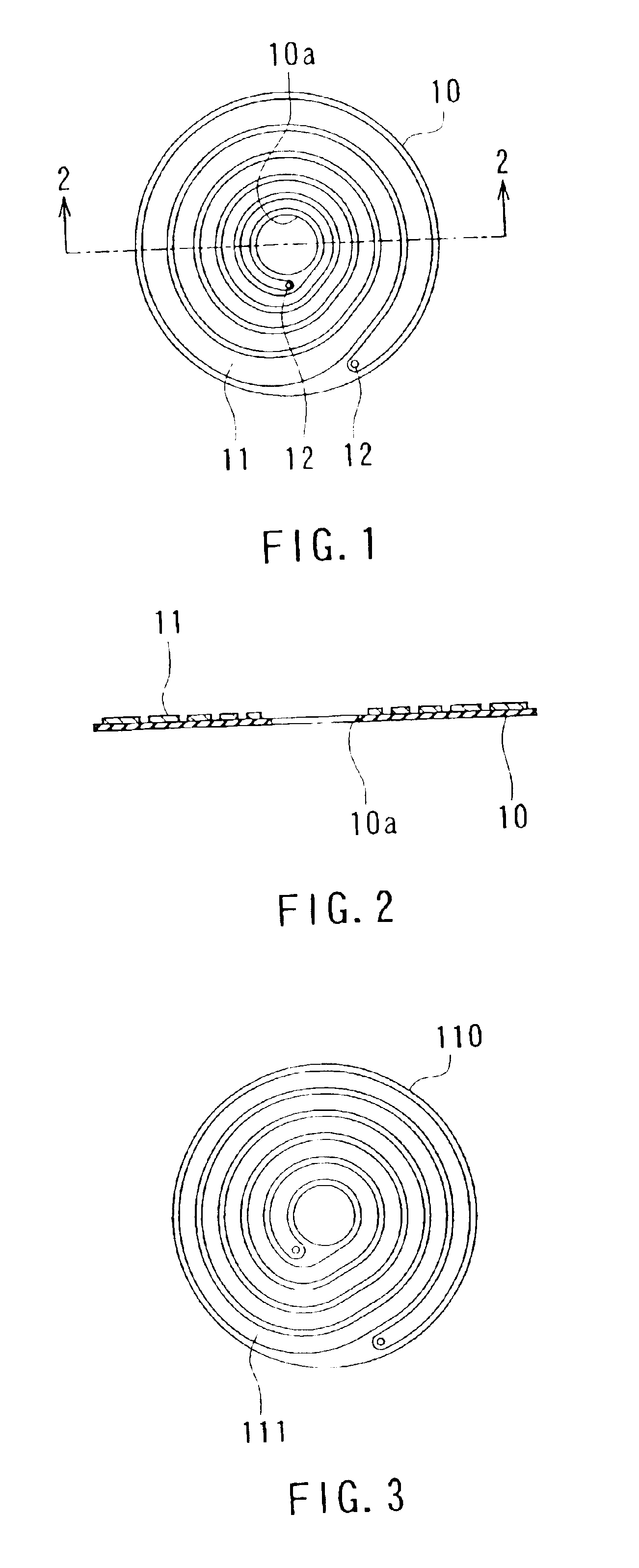
Reference is now made to FIG. 1 and FIG. 2 to describe a configuration of a planar coil according to a first embodiment of the invention. FIG. 1 is a top view of the planar coil according to the present embodiment. FIG. 2 is a cross-sectional view taken along line 2—2 of FIG. 1. The planar coil according to the embodiment comprises a disc-shaped insulating layer 10, and a winding 11 of N turns (N is an integer greater than or equal to two) formed on one of surfaces of the insulating layer 10. As an example, FIG. 1 shows the winding 11 of five turns. There is formed a circular hole 10a at the center portion of the insulating layer 10. The winding 11 is disposed in an area between the perimeter of the hole 10a and the perimeter of the insulating layer 10. The hole 10a is configured such that a core can be inserted therein.

The winding 11 is made of a patterned conductor that is formed by arranging a plate-like conductor, including a foil-like conductor, into a flat-sp...

second embodiment

[Second Embodiment]

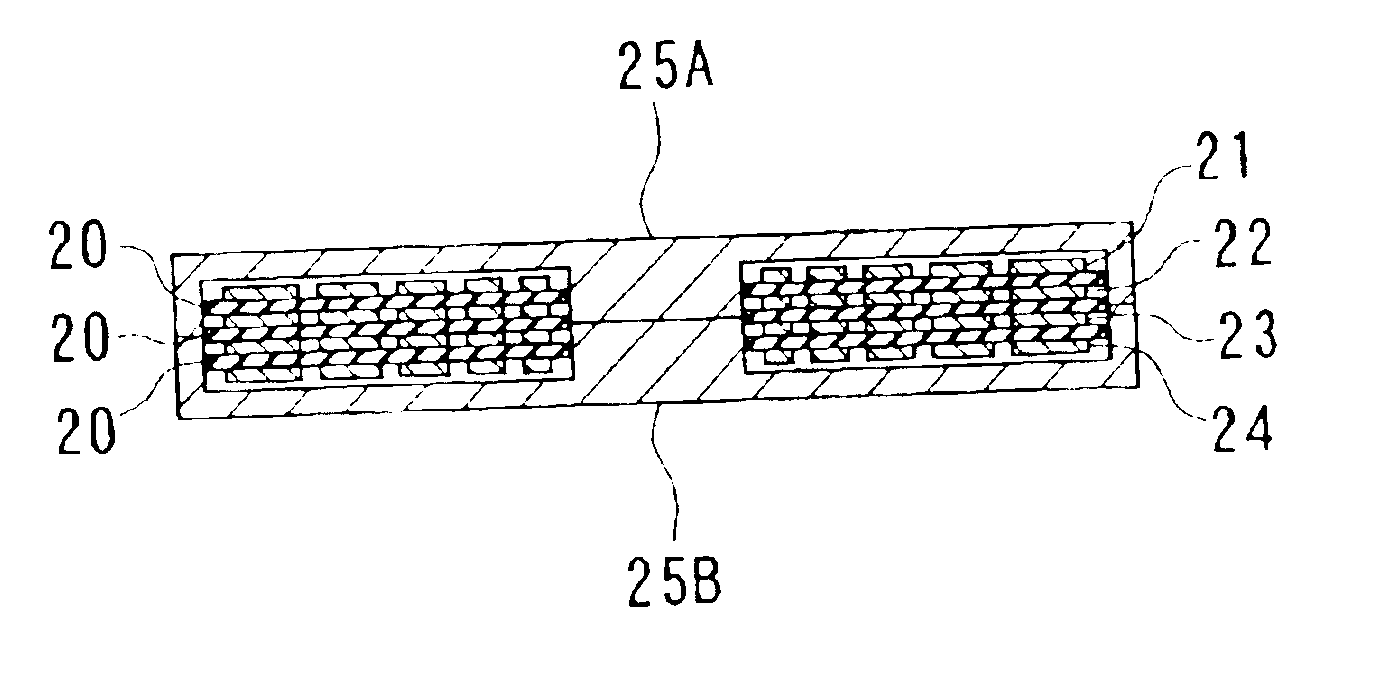
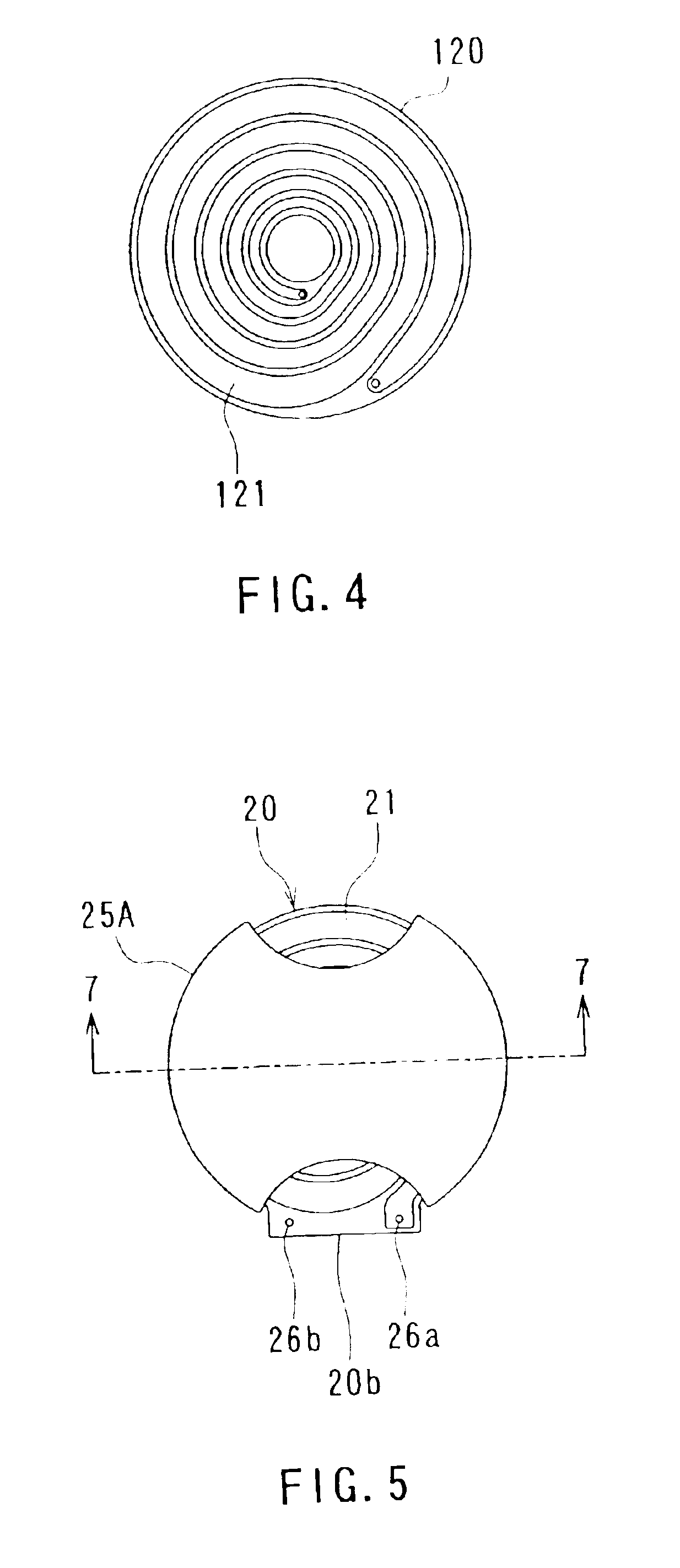
Now, description will be given of a configuration of a planar coil according to a second embodiment of the invention. FIG. 5 is a top view of the planar coil according to the embodiment; FIG. 6 is a right-hand side view of the planar coil shown in FIG. 5; and FIG. 7 is a cross-sectional view taken along line 7—7 of FIG. 5. As shown in these figures, the planar coil according to the embodiment comprises: four windings 21 to 24, stacked in the direction of thickness, each made of a patterned conductor formed of a plate-shaped conductor including a foil-shaped conductor; three insulating layers 20 each interposed between adjacent ones of the windings, and E-type cores 25A and 25B attached to a stacked body composed of the windings 21 to 24 and the insulating layers 20. For example, copper is employed as the conductor.

FIG. 8 is a top view showing the uppermost winding 21 and the insulating layer 20 below the same; FIG. 9 is a top view showing the second uppermost wind...

third embodiment

[Third Embodiment]

Now, description will be given of a configuration of a planar transformer according to a third embodiment of the invention. FIG. 13 is a top view of the planar transformer according to the embodiment; FIG. 14 is a right-hand side view of the planar transformer shown in FIG. 13; and FIG. 15 is a cross-sectional view taken along line 15—15 of FIG. 13. As shown in these figures, the planar transformer according to the embodiment comprises: four windings 31 to 34, stacked in a direction of thickness, each made of a patterned conductor formed of a plate-shaped conductor including a foil-shaped conductor; three insulating layers 30 each interposed between adjacent ones of the windings, and E-type cores 35A and 35B attached to a stacked body composed of the windings 31 to 34 and the insulating layers 30. For example, copper is employed as the conductor. The windings 31 to 34 correspond to “a plurality of windings each formed into a flat shape and stacked in a direction of...


PUM


Abstract

A planar coil includes a winding of N turns (N is an integer greater than or equal to 2). Letting ri(n) be a radius of an inner circumference of a winding portion at the nth turn (n is an integer greater than or equal to 1 and less than or equal to N) from the inner side; ro(n) be a radius of an outer circumference of the same; rmin be a radius of an inner circumference of the innermost winding portion; Wtotal be a difference between a radius of an outer circumference of the outermost winding portion and the radius of the inner circumference of the innermost winding portion; and D be a distance between winding portions at adjacent turns, the ri(n) and ro(n) are determined so as to minimize a value of A expressed by equation (1) when the rmin, Wtotla and D are given. A=n=1N(logro(n)ri(n))-1(1)

Description

TECHNICAL FIELDThe present invention relates to a planar coil and a planar transformer which have a winding that is formed by arranging a plate-like conductor into a flat-spiral shape.BACKGROUND ARTPlanar coils and planar transformers are used as choke coils and transformers in switching power supplies and the like. The planar coils and planar transformers have a winding made of a patterned conductor that is formed by arranging a plate-like conductor into a flat-spiral shape. In the planar transformers, or the planar coils having a plurality of windings, the windings are stacked in a direction of thickness, with an insulating layer interposed between adjacent ones of the windings.Among the planar coils and planar transformers, the ones that deliver relatively small output currents are formed by, for example, stacking a flat-spiral-shaped patterned conductor, an insulating layer, and a magnetic layer by thin-film forming techniques such as sputtering. On the other hand, for the ones ...

Claims


Application Information

Patent Timeline
IPC IPC(8): H01F27/28
CPCH01F27/2804H01F2027/2819
Inventor GAMOU, MASAHIROHORIKAMI, SATOSHI
Owner TDK CORPARATION
Why Eureka
Try Eureka