Nuclear fuel assembly lower tie-plate and method of its assembling

a technology of nuclear fuel and lower tie-plate, which is applied in the direction of nuclear reactors, nuclear elements, greenhouse gas reduction, etc., to achieve the effect of improving blocking performance and blocking performan

Inactive Publication Date: 2005-01-25
GLOBAL NUCLEAR FUEL-JAPAN CO LTD
View PDF11 Cites 16 Cited by
  • Summary
  • Abstract
  • Description
  • Claims
  • Application Information

AI Technical Summary

Benefits of technology

Accordingly, it is an object of the present invention to provide a nuclear fuel assembly lower tie-plate improved in performance of blocking especially straight and slim foreign substances. It is another object of the present invention to provide a method of assembling a nuclear fuel assembly lower tie-plate improved in performance of blocking especially straight and slim foreign substances.

Problems solved by technology

The foreign substances which may be expected to enter the fuel assemblies may include small metal wastes remained in the reactor primary containment system during the plant construction, metal brush pieces which have broken off during equipment cleansing and broken pieces which may be results of equipment breaches.

Method used


Image

  • Nuclear fuel assembly lower tie-plate and method of its assembling
  • Nuclear fuel assembly lower tie-plate and method of its assembling
  • Nuclear fuel assembly lower tie-plate and method of its assembling

Examples


first embodiment

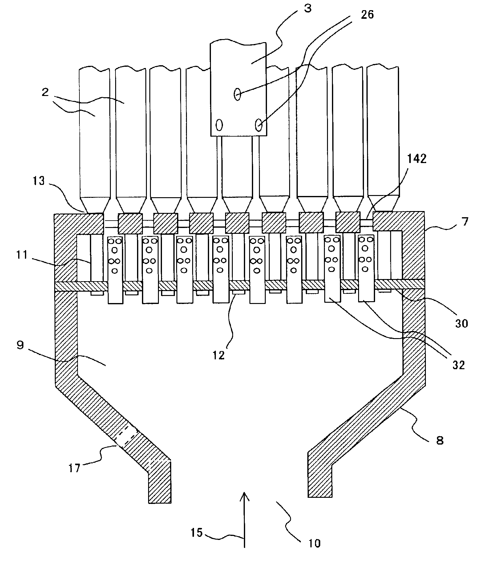
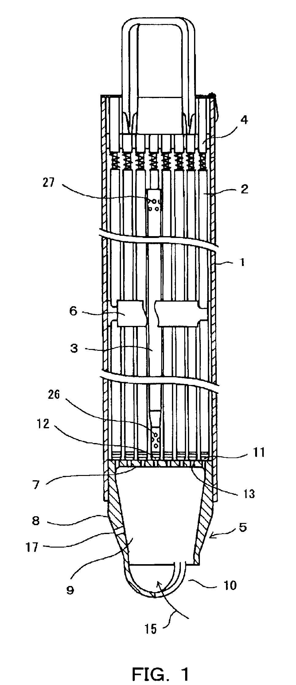
Now a lower tie-plate according to the present invention is described referring to FIGS. 4 through 7. The lower tie-plate of this embodiment is not formed as a single unit like the prior-art lower tie-plate. It is rather formed by combining separate parts of a network section 7, a nozzle section 8 and a horizontal flat plate of screening plate 30 between them by welding, for example. Many tubular filters 32 penetrate and are attached vertically to the screening plate 30. In FIG. 4, the channel box 1 (See FIG. 1) is eliminated for illustrative simplicity.

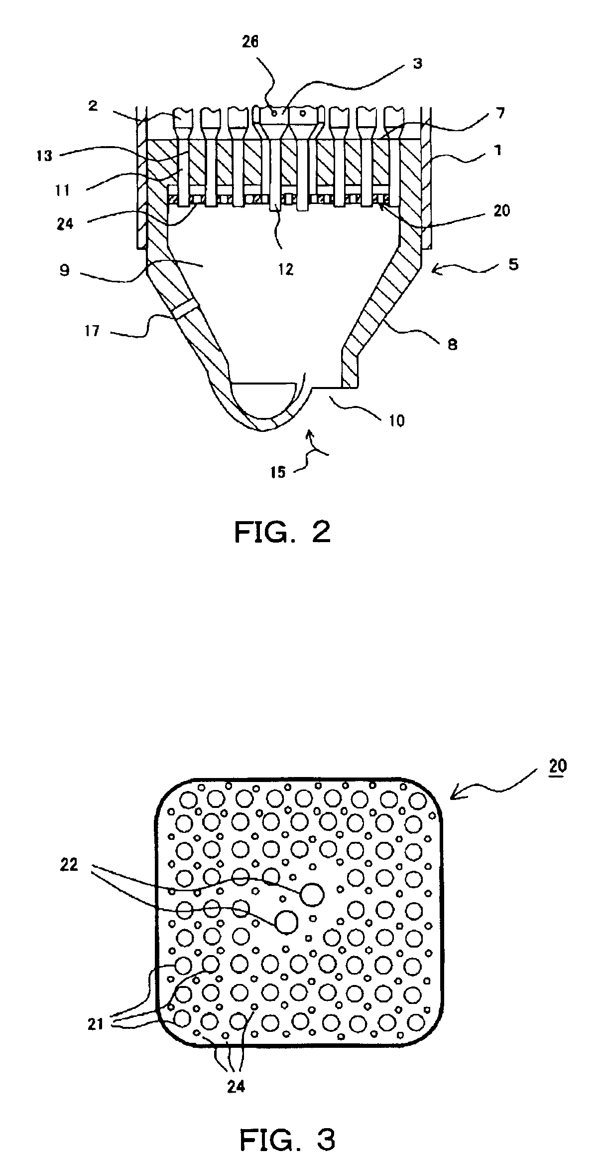
Each of the tubular filters 32 is shaped in a hollow circular cylinder, and its top end 33 is closed while its bottom end 34 is open as shown in FIG. 5. Each of the tubular filters 32 may have a diameter of 5 mm and a height of 50 mm, for example. Many small holes 36 are formed in upper part of the side wall of each of the filters 32. The diameters of the small holes 36 may be about 2 mm, for example.

Each of the filters 32 penetrates...


PUM


Abstract

A fuel assembly lower tie-plate with better performance in capturing linearly elongated foreign substances. The lower tie-plate has a screening plate positioned below the network section in the lower tie-plate cavity. The screening plate is arranged substantially horizontally so that the lower tie-plate cavity is divided into upper and lower parts by the screening plate. Tubular filters are attached to the screening plate so that the tubular filters have openings below and above the screening plate. Top ends of the tubular filters are closed, and the openings above the screening plate are formed in side walls of the tubular filters. The lower tie-plate may be assembled by combining the screening plate, the network section and the nozzle section together, after the tubular filters have been attached to the screening plate.

Description

CROSS-REFERENCE TO RELATED APPLICATIONSThis application is based upon and claims the benefits of priority from the prior Japanese Patent Application No. 2001-390855, filed on Dec. 25, 2001; the entire content of which is incorporated herein by reference.BACKGROUND OF THE INVENTIONThis invention is related generally to a lower tie-plate of a nuclear fuel assembly for a light water reactor, and more particularly to a lower tie-plate with better performance in blocking or suppressing flow of foreign substances entrained by the coolant into the fuel portion, in addition to a method of assembling it.A conventional fuel assembly for a boiling water reactor has a channel box 1 with a substantially square-shaped cross-section, as shown in FIG. 1. The channel box 1 contains a plurality of fuel rods 2 and at least one water rod 3 arranged in a square lattice. An upper tie-plate 4 and a lower tie-plate 5 are attached to the upper and lower ends of the fuel assembly, respectively. A plurality o...

Claims


Application Information

Patent Timeline
Patent Type & Authority Patents(United States)
IPC IPC(8): G21C3/32G21C3/30G21C3/33
CPCG21C3/3206Y02E30/40Y02E30/30
Inventor KAGEYAMA, TAKAOTANABE, AKIRAIWAMOTO, YUJIMASUHARA, YASUHIROFUKAHORI, TAKANORIYAMANAKA, AKIHIROMOTOTANI, AKIRA
Owner GLOBAL NUCLEAR FUEL-JAPAN CO LTD
Why Eureka
Try Eureka