
Winding arrangement with a winding body and an optical wave guide introduced therein or therethrough

Inactive Publication Date: 2005-01-25
SIEMENS AG
View PDF15 Cites 3 Cited by
  • Summary
  • Abstract
  • Description
  • Claims
  • Application Information

AI Technical Summary

Benefits of technology

To provide protection against the mechanical loading occurring within the wound body, an optical waveguide in which the light-guiding fiber is not surrounded by an otherwise customary acrylate protective layer but by some other mechanically and / or thermally more stable protective layer, at least in the area where it passes through or is introduced, is used. This protective layer then represents in particular an armoring for the light-guiding fiber. This is because the brittle acrylate normally used as the material for the protective layer, for which the brief designation PMMA is also customary, does not offer adequate mechanical protection from the mechanical loading occurring within the wound body. The brittle mechanical behavior of acrylate is also documented by a modulus of elasticity of approximately 3.3 GPa. By contrast, the material for the protective layer used instead, with a modulus of elasticity of at most 2.5 GPa, protects the optical waveguide very well from the mechanical forces occurring in the wound body. It consequently prevents destruction of the optical waveguide. The protective layer may in this case comprise entirely or only partially of this advantageous material for the protective layer.
In the case of a preferred embodiment, the optical waveguide is guided within an additional protective grommet. This additional protective grommet is very short and prevents the optical waveguide from apping off where it leaves the wound body. This increases the mechanical protection of the optical waveguide. A protective grommet, which is provided only in the outermost winding layer, also does not lead to an increased flashover tendency.
It is favorable if the material for the protective layer has a modulus of elasticity of at most 1.5 GPa. This further increases the mechanical protective effect.
In addition, there is also an embodiment in which the material for the protective layer has an inorganic solids content. The inorganic solids content improves both the mechanical stability and the thermal stability. In particular, inorganic solids content in the material for the protective layer of at least 50% is favorable. This is because the permissible maximum operating temperature increases with the inorganic solids content.
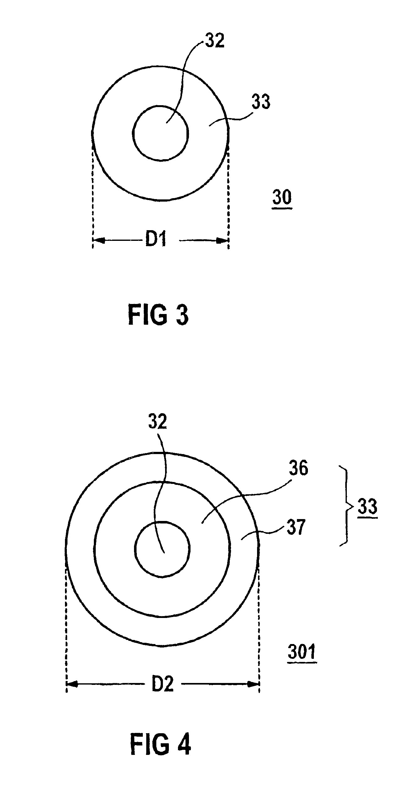
A variant in which the protective layer comprises two plies is favorable. This allows the protective layer to be designed both with regard to the requirement for adhesion on the light-guiding fiber and with regard to the requirement for mechanical and thermal stability. In particular, it is preferred if the first ply, which is applied directly to the optical fiber, comprises of polyimide and the second fiber, applied to the latter, comprises of the material for the protective layer. In particular, polyimide has very good adhesive properties on the optical fiber in the form of a glass fiber. Furthermore, polyimide can be used in a very wide temperature range from −190° C. to +385° C. The material for the protective layer, provided for the second ply, then primarily has the purpose of providing adequate mechanical protection.

Problems solved by technology

This is because the brittle acrylate normally used as the material for the protective layer, for which the brief designation PMMA is also customary, does not offer adequate mechanical protection from the mechanical loading occurring within the wound body.

Method used


Image

  • Winding arrangement with a winding body and an optical wave guide introduced therein or therethrough
  • Winding arrangement with a winding body and an optical wave guide introduced therein or therethrough
  • Winding arrangement with a winding body and an optical wave guide introduced therein or therethrough

Examples


Embodiment Construction

Reference will now be made in detail to the preferred embodiments of the present invention, examples of which are illustrated in the accompanying drawings, wherein like reference numerals refer to like elements throughout.

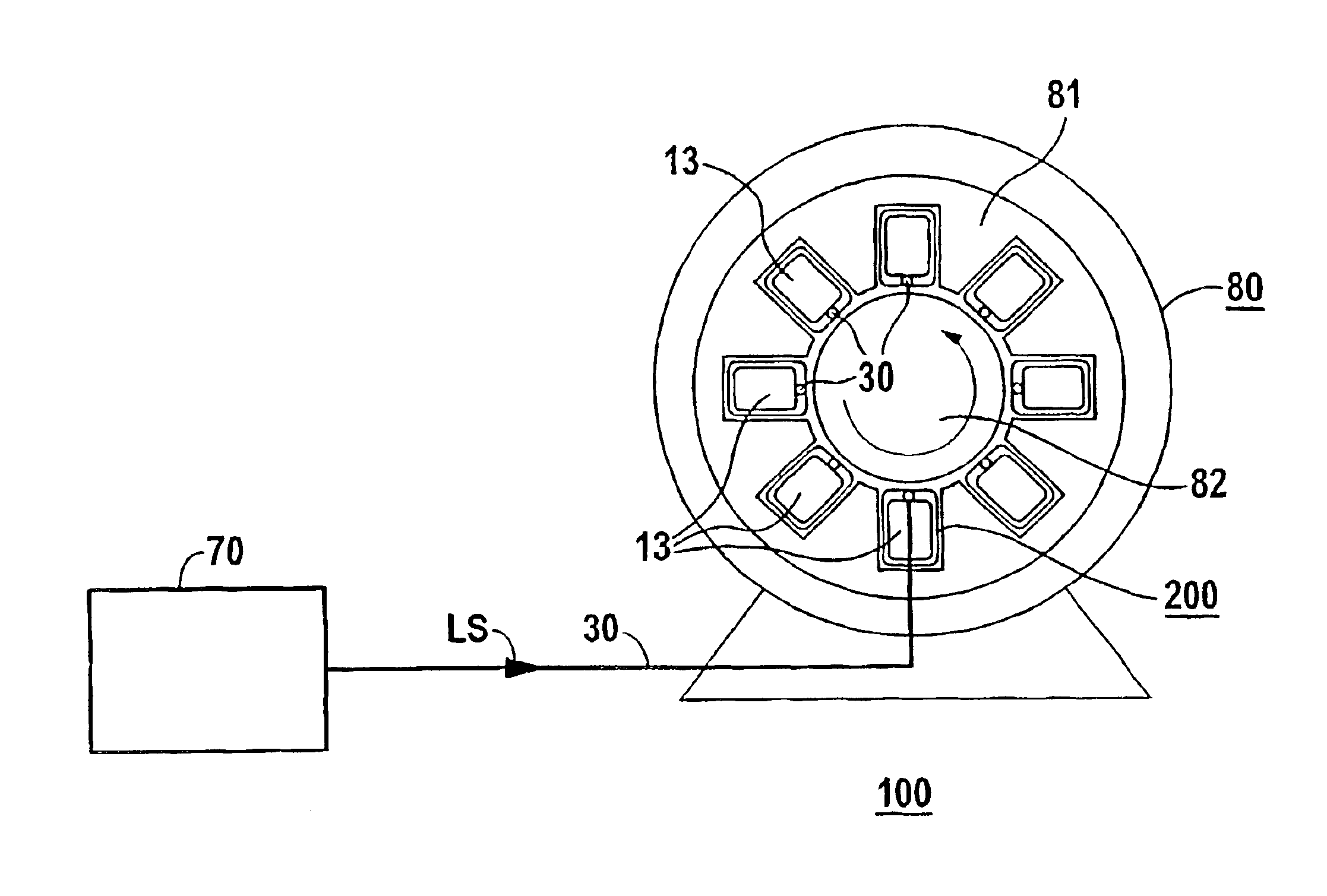
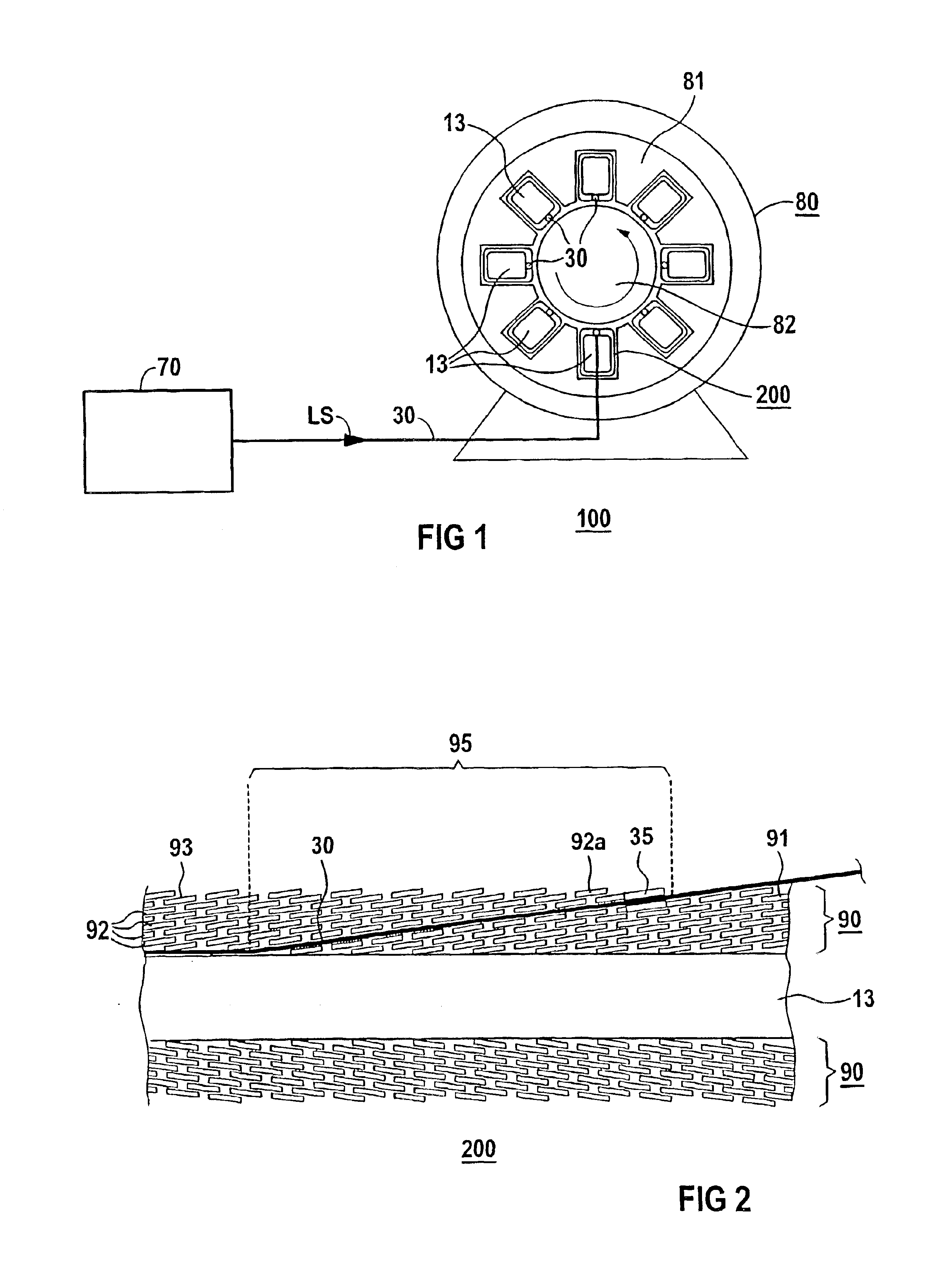
Parts corresponding to one another are provided with the same reference numerals in FIGS. 1 to 4.

Indicated in FIG. 1 is an electrical generator 80, which comprises a stator 81 and a rotor 82. The electrical generator 80 is monitored by an optical measuring device 100, which is intended for optical measured variable acquisition with the generator 80. The optical measuring device 100 includes an evaluation device 70, which is arranged outside the generator 80 and is optically connected to the interior of the generator 80, in particular to the stator 81, via an optical waveguide 30. By a light signal LS transmitted via the optical waveguide 30, at least one optical measuring point in the generator 80 is interrogated. The electrical generator 80 represented in FIG. 1 i...


PUM


Abstract

A winding arrangement comprising at least one multi-layered winding body having a plurality of windings associated with a winding band and an optical waveguide, which is introduced therein or therethrough. The optical waveguide is wound into the winding body in the area where it is introduced therein and comprises, at least in the area, a light-guiding fiber and a protective layer applied thereto. The protective layer consists either entirely or partially of a layer of material having a maximum elasticity module of 2.5 GPa.

Description

BACKGROUND OF THE INVENTIONOne aspect of the invention relates to a winding arrangement with at least one multi-layered wound body comprising a large number of windings of at least one winding band and an optical waveguide passed through the wound body or introduced into the wound body.Such a winding arrangement may be used for example in an optically monitored electrical device in the area of electrical power generation and distribution. The electrical device may in this case be designed as an electrical generator or else as an electrical transformer. Such an electrical device represents a very expensive and long-term investment. Its failure may entail very high costs. Therefore, the use of a diagnostic system, which may in particular also comprise an optical measuring device, is increasingly being considered for the early detection of defects, such as for example overheating or electrical flashover. The structural design of the device used in electrical power generation is current...

Claims


Application Information

Patent Timeline
IPC IPC(8): G02B6/36H02K11/00H02K3/14H02K3/12G02B6/44H02K11/20H02K11/25H02K11/33H02K11/35H02K29/08
CPCG02B6/4457H02K11/0078H02K11/0047H02K3/14H02K11/001H02K29/08H02K11/0073H02K11/20H02K11/25H02K11/33H02K11/35
Inventor BOSSELMANN, THOMASTHEUNE, NILS
Owner SIEMENS AG
Learn More