Method for computer-aided layout of manufacturing cells

Inactive Publication Date: 2005-01-25
GM GLOBAL TECH OPERATIONS LLC
View PDF6 Cites 119 Cited by
  • Summary
  • Abstract
  • Description
  • Claims
  • Application Information

AI Technical Summary

Problems solved by technology

However, creation of collision-free motions between these step

Method used


Image

  • Method for computer-aided layout of manufacturing cells
  • Method for computer-aided layout of manufacturing cells
  • Method for computer-aided layout of manufacturing cells

Examples


Embodiment Construction

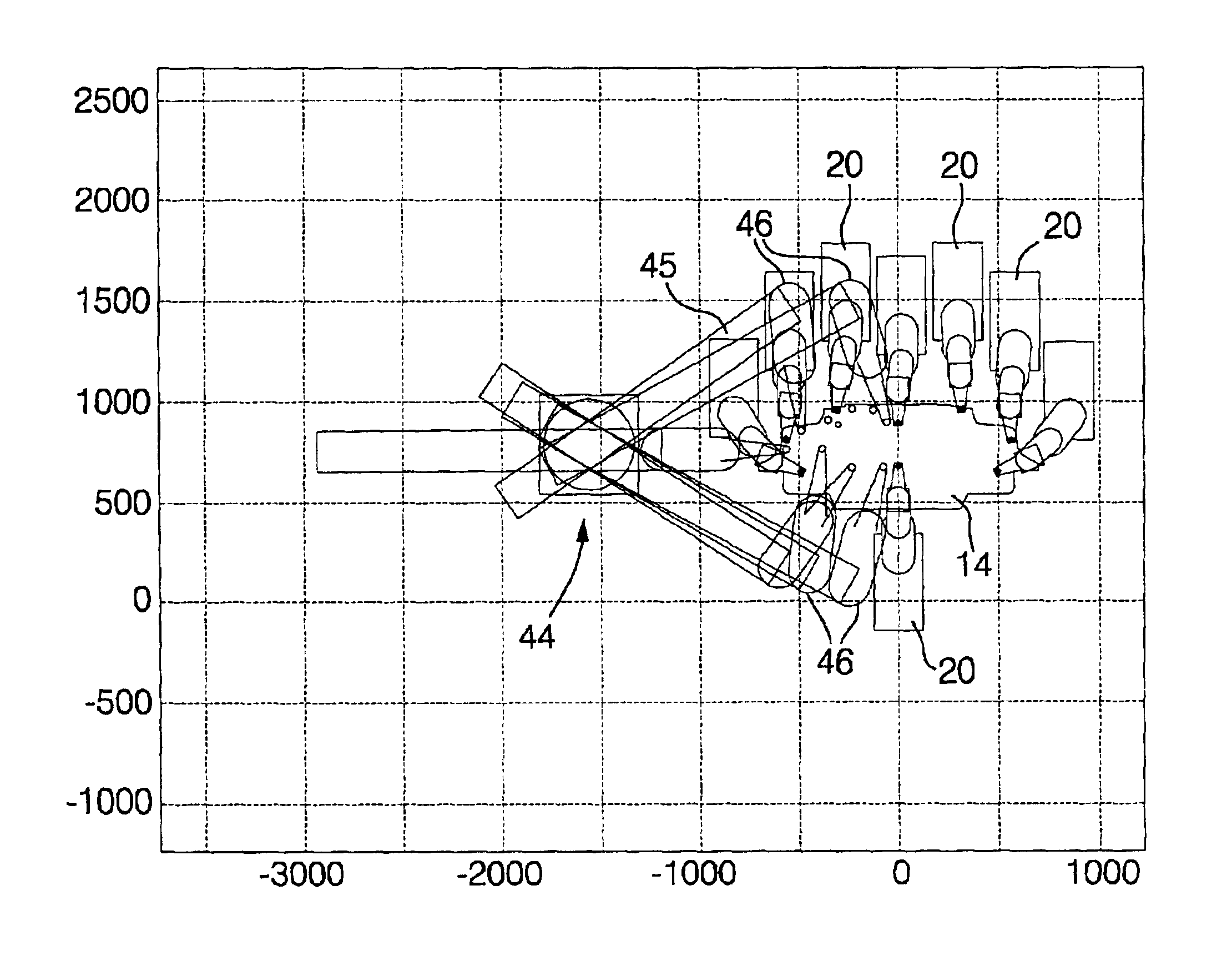
The practice of the process of this invention will be illustrated in the locating of two sheet metal stampings that are to be precisely superimposed and welded in a manufacturing cell dedicated to welding different but structurally similar parts. For simplicity and clarity of illustration and description, the process will be described in joining two tail panel pieces for a single model of automobile. However, it is to be understood that, in many situations, the subject process would be used to layout the necessary equipment in a manufacturing cell for positioning and welding tail panel assemblies, or the like, for several different vehicles.

Description of Workpieces and Tools for the Manufacturing Cell

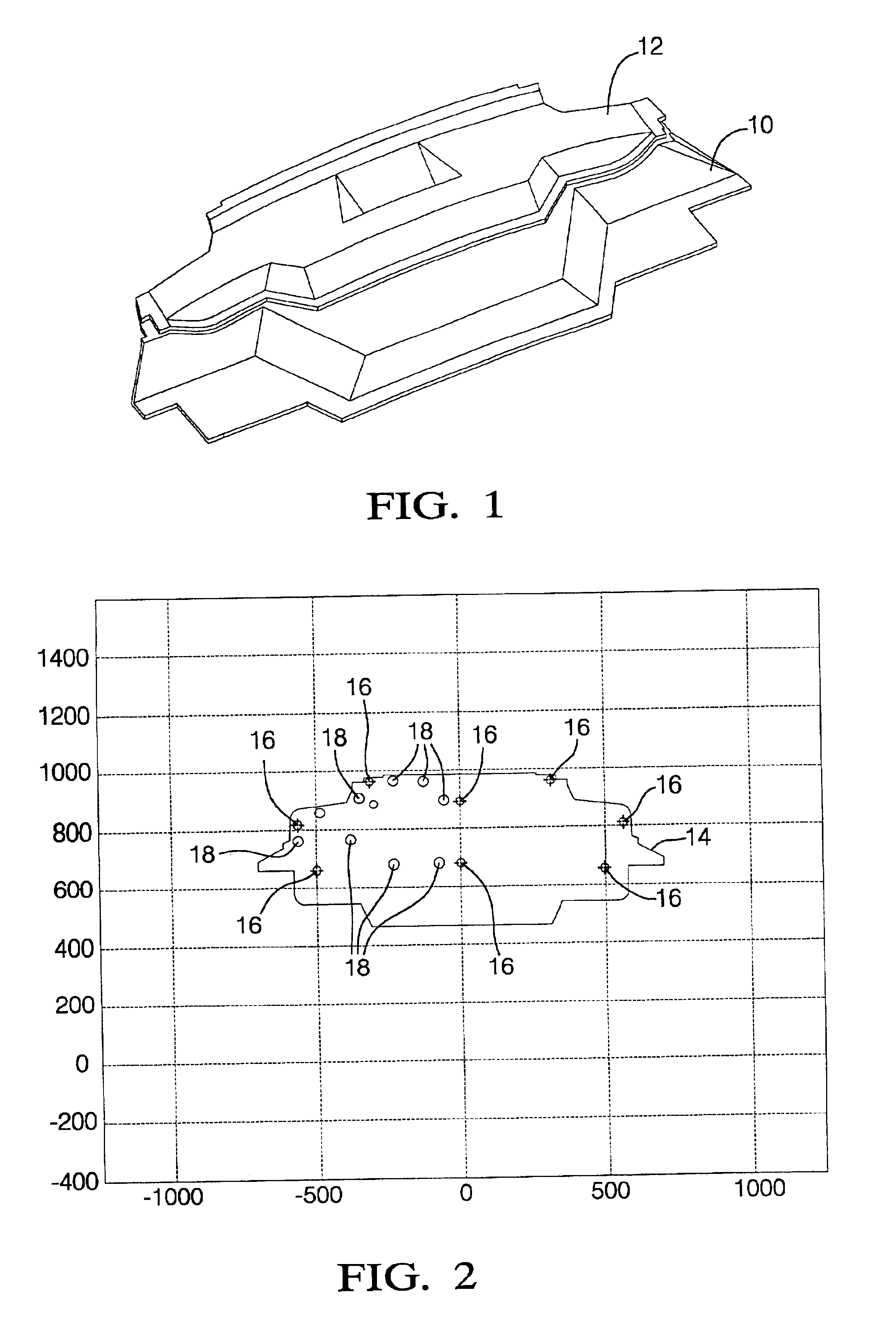
FIG. 1 shows inner 10 and outer 12 tail panel stampings. The stampings are typically stamped and trimmed from a sheet of suitable steel or aluminum alloy. The inner and outer panels would then be juxtaposed as shown in FIG. 1 and welded together to form a tail panel assembly. Later, th...


PUM


Abstract

A computer assisted method is disclosed for making an optimized layout of a manufacturing cell to be used, for example, to locate, hold and process workpieces, such as in robotic welding of an assembly of stamped sheet metal parts. The items to be processed and employed in the cell are identified by physical structure and kinematic characteristics and given an initial location to start the process. Further movements of the parts toward attraction points and away from repelling points are evaluated on the computer by an optimization program to arrive at an optimized cell layout.

Description

TECHNICAL FIELDThis invention pertains to processes for computer-aided layout of workpiece holding and joining operations in the assembly of manufactured parts.BACKGROUND OF THE INVENTIONA manufacturing cell for automotive body assembly has multiple devices that work in close proximity. Stamped sheet metal parts, or the like, are loaded into a fixture consisting of many locating pins and clamps. The clamps close to hold the parts immobile and in proper alignment and then machinery to join the parts moves to engage them. The most common joining technique is resistance spot welding in which a welding gun is moved from welding location to location, manually or robotically. Similar workpiece holding and joining operations are performed in the manufacture of many products.A new development in such manufacturing operations is the availability of programmable fixtures for parts to be joined. Fixturing elements are carried by programmable robotic devices and can thus be repositioned for pro...

Claims


Application Information

Patent Timeline
IPC IPC(8): G06F17/50G05B19/4069
CPCG05B19/4069G05B2219/45104G05B2219/40479G05B2219/32085Y02P90/02
Inventor WAMPLER, II, CHARLES W.
Owner GM GLOBAL TECH OPERATIONS LLC
Why Eureka
Try Eureka