Stretch head for facilitating wrapping palletized loads

a technology of stretch head and palletized load, which is applied in the direction of wrapping, web handling, transportation and packaging, etc., can solve the problems of inability to move easily, slippage, etc., and achieve the effect of not being able to move readily

Inactive Publication Date: 2005-02-01
SIGNODE IND GRP
View PDF20 Cites 39 Cited by
  • Summary
  • Abstract
  • Description
  • Claims
  • Application Information

AI Technical Summary

Benefits of technology

The foregoing and other objectives are achieved in accordance with the teachings and principles of the present invention through the provision of a new and improved wrapping film stretch head which comprises a support frame, upon which the stretch head is mounted, wherein the support frame is mounted at a predeterminedly inclined angle upon a vertically oriented downright or mast-type support structure. A wrapping film supply roll is mounted upon a first end of the stretch head, while a discharge or dispensing idler roller is mounted upon a second opposite end of the stretch head whereby, due to the aforenoted inclination of the support frame with respect to the vertically oriented downright or mast-type support structure, the dispensing idler roller is located at a lower elevational position than that of the wrapping film supply roll. In accordance with the improvement of the present invention, an additional belted or sleeved roll

Problems solved by technology

In addition, the provision of the belted sleeve upon the belted or sleeved roller causes the wrapping film to effectively adhere to the belted sleeve material whereby, while

Method used


Image

  • Stretch head for facilitating wrapping palletized loads
  • Stretch head for facilitating wrapping palletized loads
  • Stretch head for facilitating wrapping palletized loads

Examples


Embodiment Construction

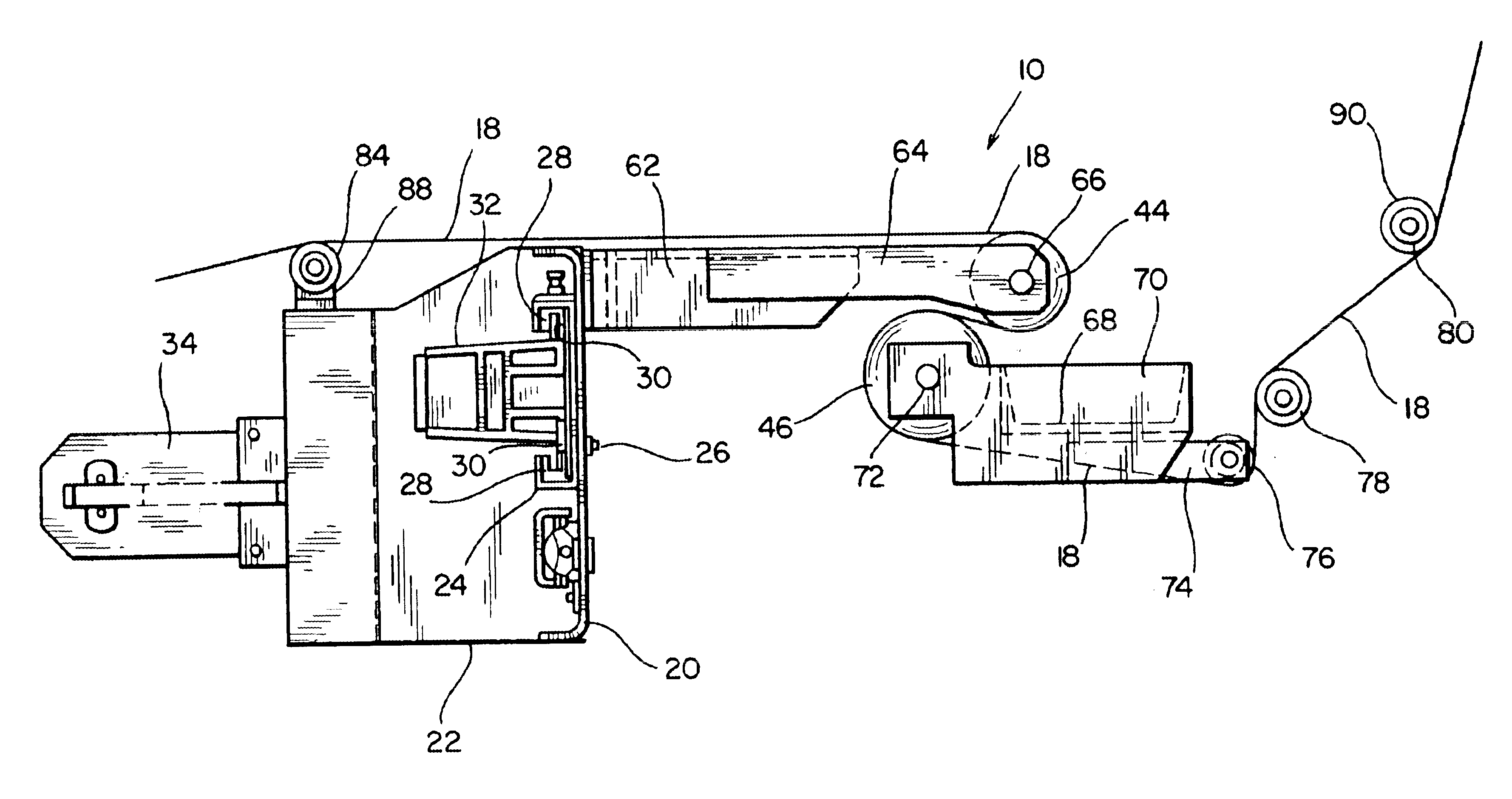
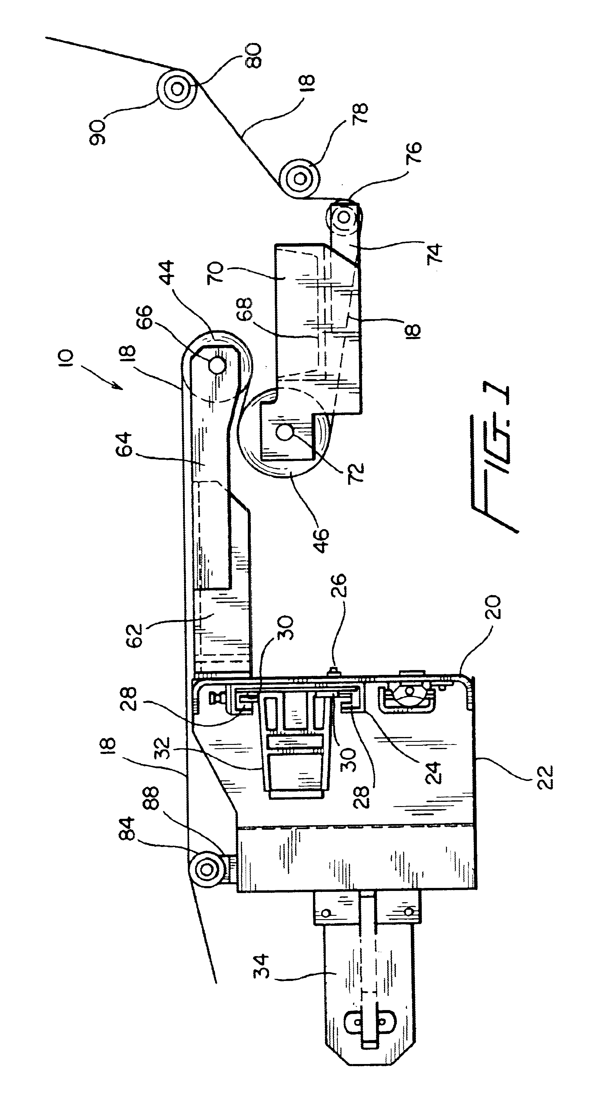
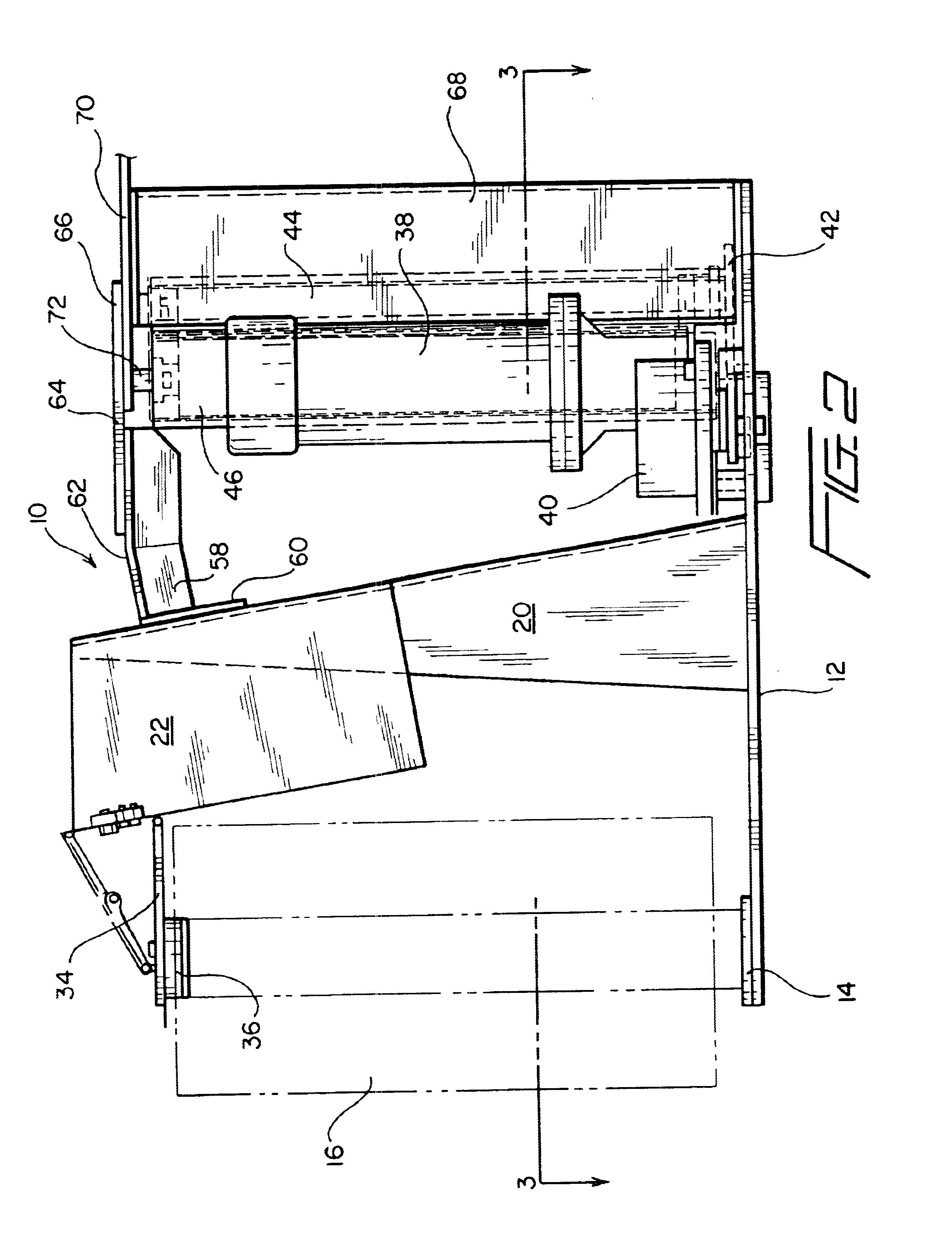
Referring now to the drawings, and more particularly to FIGS. 1-3 thereof, the new and improved wrapping machine stretch head, constructed in accordance with the principles and teachings of the present invention, is disclosed and is generally indicated by the reference character 10. The stretch head 10 is seen to comprise a base plate 12, as best seen in FIGS. 2 and 3, upon one end of which a lower bearing member 14 is mounted so as to rotatably support a substantially upstanding or vertically oriented wrapping film supply roll 16 from which a fresh supply of wrapping film 18 is able to be withdrawn in connection with the performance of, for example, a palletized load wrapping operation comprising a palletized load disposed upon a support pallet, not shown. A substantially upstanding or vertically oriented main support frame 20 projects upwardly from a substantially central portion of the base plate 12, and a steel sheet housing 22 is integrally fixed to and carried by the main supp...


PUM

PropertyMeasurementUnit
Angleaaaaaaaaaa
Tensionaaaaaaaaaa
Elevationaaaaaaaaaa

Abstract

A stretch head for facilitating the wrapping of palletized loads within packaging or wrapping film comprises a vertical downright, and a carriage assembly vertically movable along the vertical downright. A base plate is mounted upon the carriage assembly and is inclined with respect to a horizontal plane so as to have a first end thereof disposed at a higher elevation than a second opposite end thereof. A supply roll of wrapping or packaging film is rotatably mounted upon the first higher end of the base plate, and a pair of tension rollers are mounted upon a substantially central portion of the base plate. A strain gauge roller is also mounted upon the base plate for receiving the wrapping film exiting from the tension rollers, a first idler roller is mounted upon the base plate for receiving the wrapping film from the strain gauge roller, and a second idler roller is mounted upon the second opposite end of the base plate for receiving the wrapping film from the first idler roller. Since the second idler roller is mounted upon the lowest end portion of the base plate, in view of the inclined disposition thereof, the second idler roller is capable of positioning the wrapping film at the lowest elevation whereby the wrapping film can be wrapped around the lowermost regions of the palletized load. The second idler roller also comprises a rubberized sleeve member for preventing movement of the wrapping film in an axial direction along the external periphery of the second idler roller so as to ensure proper positioning and orientation of the wrapping film with respect to the palletized load.

Description

FIELD OF THE INVENTIONThe present invention relates generally to stretch film wrapping machines, and more particularly to a new and improved wrapping machine stretch head wherein the stretch head is provided with a belted or sleeved control roller which permits the film wrapping material being dispensed from a supply roll of film wrapping material to be positionally controlled and, in particular, to enable the dispensed film to be capable of being applied to a palletized load at an elevational level which is within a predetermined distance from the bottom of the pallet or above the support surface upon which the pallet is supported.BACKGROUND OF THE INVENTIONFilm wrapping machines for wrapping products, articles, packages, or the like, in wrapping film conventionally comprise a film roll upon which a supply of the wrapping film is disposed, and a plurality of rollers around which the wrapping film is routed so as to have a predetermined amount of tension developed within the film su...

Claims


Application Information

Patent Timeline
IPC IPC(8): B65B11/02B65B41/00B65B11/04B65B11/00B65B41/16B65H23/04B65H23/188
CPCB65B11/00B65B11/045B65B41/16B65H23/044B65H23/1888B65H2403/30B65H2301/3112B65B2011/002
Inventor FREY, MICHAEL R.
Owner SIGNODE IND GRP
Why Eureka
Try Eureka