Method and apparatus for removing hazardous liquid from petroleum tanker trailer delivery/loading piping

a technology for petroleum tanker trailers and hazardous liquids, applied in liquid handling, instruments, packaged goods types, etc., can solve problems such as accounting headaches, severe injury or death, and major property damage, and achieve the effects of reducing the cost of providing, simplifying the packaging of evacuation system components, and reducing the cost of the system

Active Publication Date: 2005-02-01
FRANKLIN FUELING SYST
View PDF16 Cites 19 Cited by
  • Summary
  • Abstract
  • Description
  • Claims
  • Application Information

AI Technical Summary

Benefits of technology

According to a further feature of the invention, the system further includes a vapor return line extending between the cargo tank and the external conduit and connected to the external conduit by a fitting and the fitting is located in the module. This arrangement eliminates the need to purchase customized and expensive API heads in order to achieve an evacuation capability.
According to a further feature of the invention, the module comprises a sight glass positioned between the free end of the conduit and the coupling device. This arrangement further reduces the cost of providing the evacuation capability by utilizing existing system hardware.
According to a further feature of the invention, the sensor and drain are positioned in an annular wall of the sight glass. This specific arrangement simplifies packaging of the evacuation system components and further reduces the cost of the system.

Problems solved by technology

Accordingly a collision proximate the wet lines can spill up to 75 gallons of flammable liquid and can cause severe injury or death along with major property damage.
The problem with this approach is one of weights and measures.
Since the tanker trailer is effectively considered as having received the fuel in the wet lines, pumping this fuel back into the supply tank produces accounting headaches and requires that the fuel that is siphoned off be measured and credit given accordingly.
This is both a complex and costly undertaking.
This however is economically unattractive since it adds significant weight to the tanker trailer which translates into lower fuel cavity capacity.
This procedure requires tremendous pressure to force the fuel back into the housing tank against the downward gravity force of the fuel in the housing tank.
As a result, powerful pumps or other mechanisms have to be made available, greatly adding to the cost of the filling and unloading operations.

Method used


Image

  • Method and apparatus for removing hazardous liquid from petroleum tanker trailer delivery/loading piping
  • Method and apparatus for removing hazardous liquid from petroleum tanker trailer delivery/loading piping
  • Method and apparatus for removing hazardous liquid from petroleum tanker trailer delivery/loading piping

Examples


Embodiment Construction

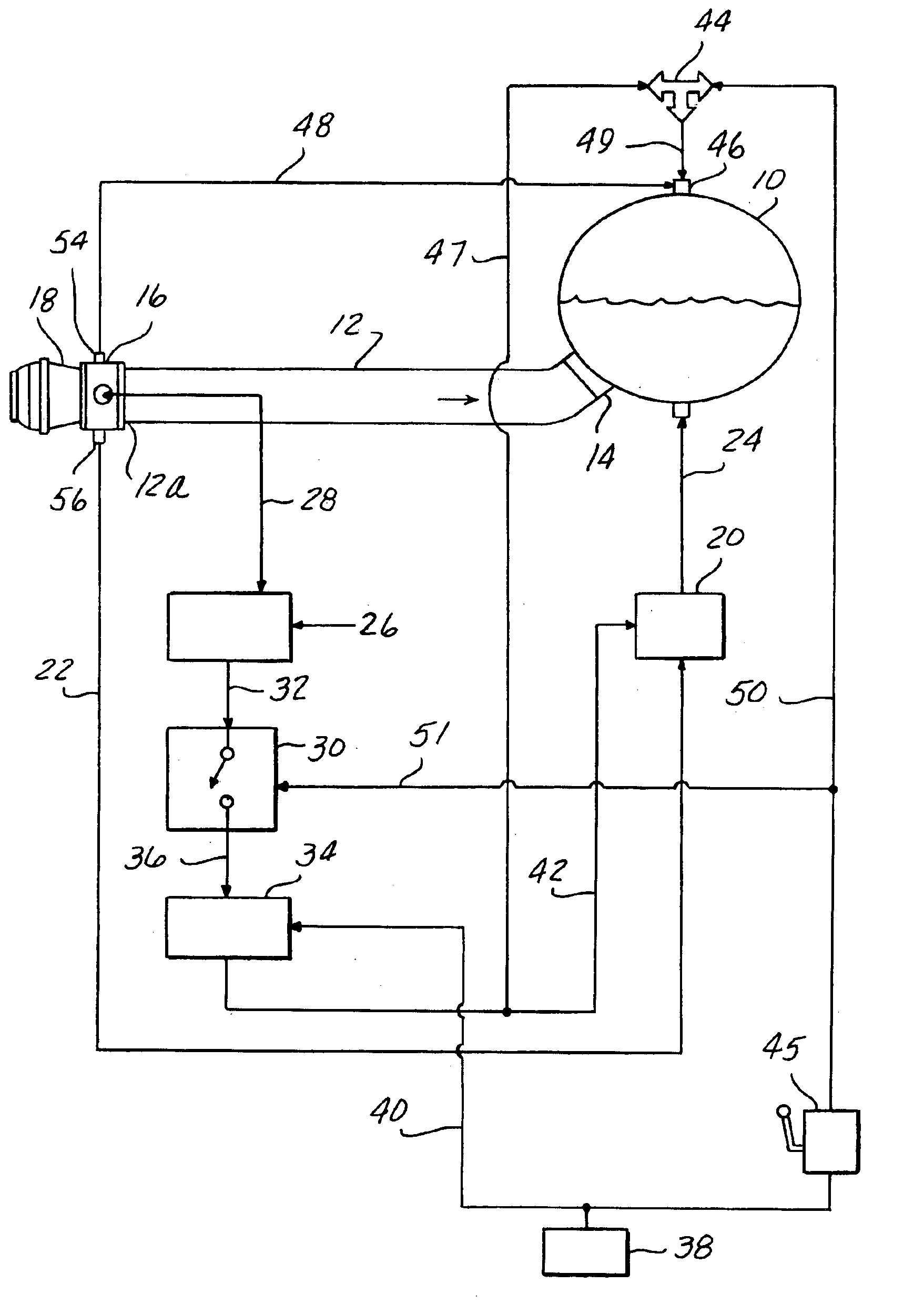
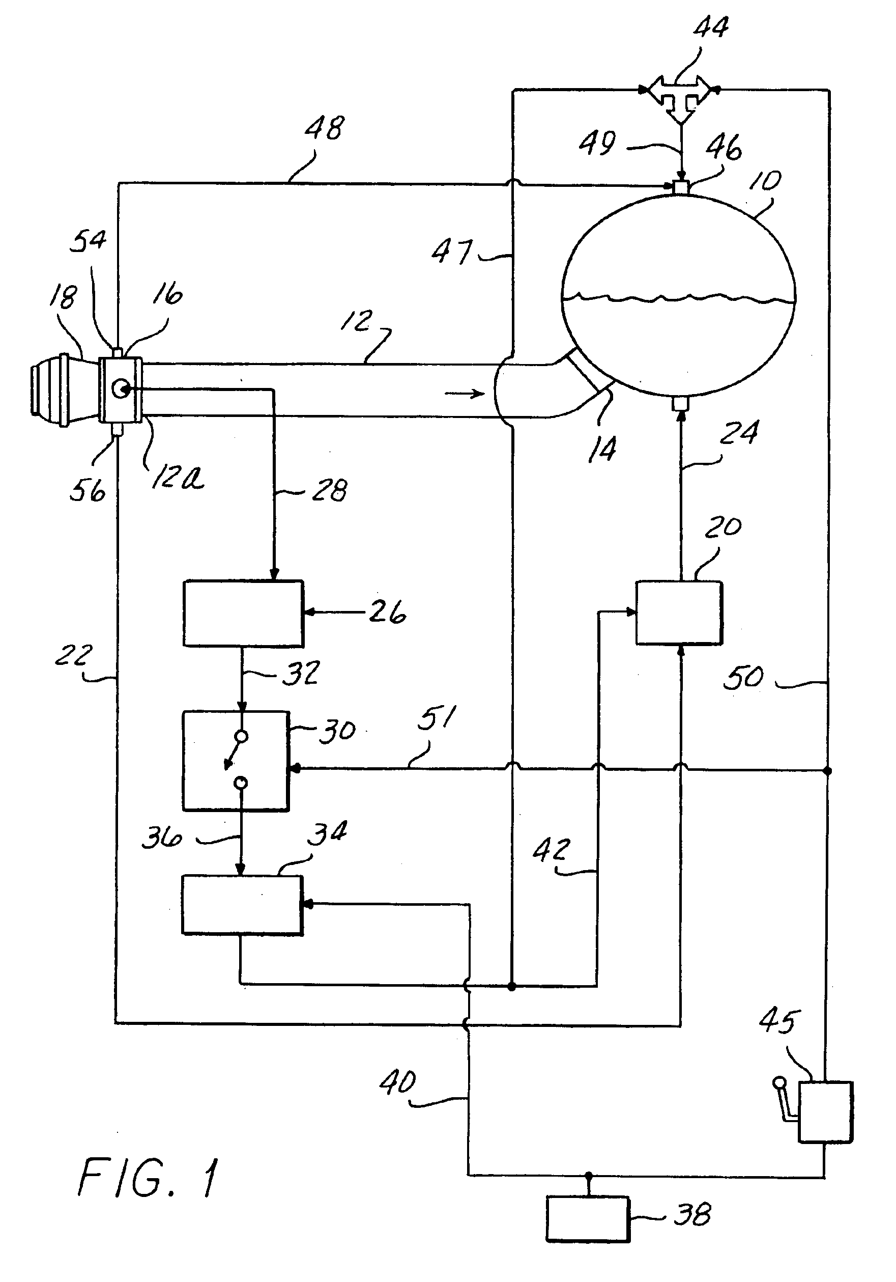
FIG. 1 shows schematically a delivery / loading system for a cargo tank 10 of a road tanker vehicle with provision to evacuate the delivery / loading line or “wet line.”

The evacuation system of FIG. 1 includes a bottom loading cargo tank 10 of a road tanker vehicle; a wet line 12 to facilitate delivery / loading of the cargo tank; a valve 14 connecting the inboard end of the wet line 12 to the bottom of the cargo tank 10; a sight glass module 16 positioned at the outboard end 12a of the wet line 12; an API (American Petroleum Institute) head 18 positioned outboard of the module 16; a suction pump 20; an evacuation line 22 interconnecting module 16 and suction pump 20; a discharge line 24 connecting the discharge of pump 20 and the bottom of the tank 10; an optic control system (OCS) controller 26; a lead 28 interconnecting module 16 and the input of OCS controller 26; an air switch 30; a lead 32 interconnecting the output of OCS controller 26 and air switch 30; a solenoid valve 34; a lead...


PUM

PropertyMeasurementUnit
diameteraaaaaaaaaa
flammableaaaaaaaaaa
weightsaaaaaaaaaa

Abstract

A method and system is provided for removing hazardous liquid from a wet line of a cargo tanker truck. The system includes a sight glass module positioned at the outboard end of the wet line. The sight glass module includes a vent, a drain, and an optical sensor. When the optical sensor senses liquid in the module, a control system operates to pump the liquid from the drain into the cargo tank.

Description

BACKGROUND OF THE INVENTIONA petroleum tanker trailer utilizes large diameter piping or “wet lines” for delivery of flammable product to service stations as well as for loading product into the trailer. After the trailer is loaded, up to 75 gallons of flammable liquid remain in the wet lines. Accordingly a collision proximate the wet lines can spill up to 75 gallons of flammable liquid and can cause severe injury or death along with major property damage.Various approaches have been proposed to address this problem. One solution is to drain the fluid from the wet lines after filling. The problem with this approach is one of weights and measures. Since the tanker trailer is effectively considered as having received the fuel in the wet lines, pumping this fuel back into the supply tank produces accounting headaches and requires that the fuel that is siphoned off be measured and credit given accordingly. This is both a complex and costly undertaking.Another approach is to provide a pro...

Claims


Application Information

Patent Timeline
Patent Type & Authority Patents(United States)
IPC IPC(8): B65B1/04B60P3/22
CPCB60P3/2245B60P3/2265B60P3/2255
Inventor BAY, ANDREW T.SCHUGARS, SCOTT BRADLEY
Owner FRANKLIN FUELING SYST
Why Eureka
Try Eureka