Optical cable installation with cable lubricator

a technology of optical cable and lubricator, which is applied in the direction of cables, cables, instruments, etc., can solve the problems of high installation cost, time-consuming splicing, and inability to have a large number of splice joints, and achieve the effect of less stiffness

Inactive Publication Date: 2005-02-01
NKF KABEL BV
View PDF32 Cites 22 Cited by
  • Summary
  • Abstract
  • Description
  • Claims
  • Application Information

AI Technical Summary

Benefits of technology

The present invention consists of a serially connected lubricator with foam-plugs and suitable lubricant, installed in the duct downstream of pushing / blowing cable launching equipment. The lubricator operates under pressure and the airflow, needed to blow the cable, is bypassed into the duct. Guide blocks to avoid buckling of the cable when pushed through the relatively large lubricating chamber are provided. The latter is especially important for smaller diameter cable with less stiffness.

Problems solved by technology

Splices are time consuming to make and incur considerable installation costs.
Moreover, it is not desirable to have a large number of splice joints in view of the relatively substantial signal damping caused by each joint in proportion to the total signal damping of the overall signal path.
Even so, frictional effects have limited the installation lengths attainable by pushing and blowing techniques.
Here the mini-tubes become smaller and smaller, making it more difficult to lubricate with foam-plugs.
More importantly, blowing many cables from one point to many different end-locations (houses or offices), and lubricating them with a blown foam plug every time, is rather impractical.
Pre-lubricated ducts (by the manufacturer) have turned out not to be always reliable.

Method used


Image

  • Optical cable installation with cable lubricator
  • Optical cable installation with cable lubricator
  • Optical cable installation with cable lubricator

Examples


example 1

PBTP 2.0 mm Cable in Un-Lubricated Ribbed 4 mm Tube

First attempt: Un-lubricated installation. Blowing transport of cable started with a rate of advance of 35 m / min but stopped because of frictional resistance after reaching only 50 m in the duct trajectory.Second attempt: Lubricating the tube with water-based lubricant and a foam-plug blown through. Blowing transport of cable started with a rate of advance of 35 m / min and the speed had dropped to 7 m / min after reaching 225 m in the duct trajectory.Third attempt: Using the cable lubricator (and another unlubricated tube). Blowing started with 35 m / min and the speed had dropped to 8 m / min after reaching 500 m in the duct trajectory.

example 2

Nylon 1.8 mm Cable in Pre-Lubricated Ribbed 4 mm Tube

First attempt: Installation with no further lubricating. Blowing started with 35 m / min and the speed dropped to 5 m / min at reaching 235 m in the duct trajectory.Second attempt: Using the cable lubricator (and another unlubricated tube). Blowing started with 35 m / min and the speed was still the same upon reaching 585 m in the duct trajectory while the pressure was only 7 bars.

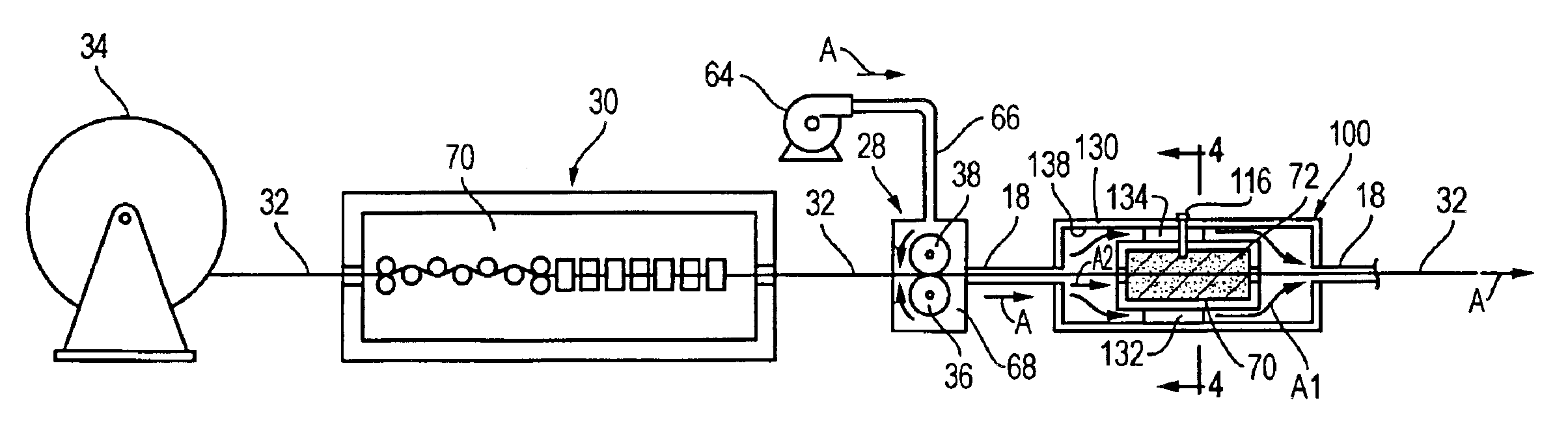
The effect of post-launch lubrication with the pressurized cable lubricator 100 is an improvement by a factor of 10 or more in blowing length with respect to the non-lubricated case. Moreover the blowing results reproduce better when using the cable lubricator. The blowing distance improvement of the cable lubricator is also much more striking than the improvement of lubricating the guide tubes alone (or using pre-lubricated tubes), which was an unexpected and surprising improvement.

For the sake of completeness, it is further noted that the lubrication method ...


PUM


Abstract

A cable is installed in a guide tube by means of blowing (and, optionally, synergetic pushing) and lubricating the cable during this installation. Lubricating the cable is done after the cable has passed the cable blowing equipment and hence takes place in a pressurized airflow passage. A hollow chamber filled with foam-plugs saturated with lubricant forms the cable lubricator. To avoid buckling, cable guide blocks are placed, which also divide the lubricator in different sub-chambers, each with its own foam-plug and content of lubricant. The airflow, needed to propel the cable during blowing, can bypass the lubricator.

Description

CROSS-REFERENCE TO RELATED APPLICATIONSNot applicable.STATEMENT REGARDING FEDERALLY SPONSORED RESEARCH OR DEVELOPMENTNot applicable.BACKGROUND OF THE INVENTIONThis invention relates generally to optical telecommunications networks, and in particular to methods and apparatus for installing fiber optic communication cables in ducts and conduits, including underground ducts and guide tubes that channelize the underground ducts.Various factors must be considered when a fiber optic cable is installed in a protective duct. Some major concerns are the ease of installation and reduction in the amount of time needed to install the cable. Generally, it is desirable to install the longest continuous length of cable possible to reduce the number of splices needed for the cable run. Splices are time consuming to make and incur considerable installation costs. Moreover, it is not desirable to have a large number of splice joints in view of the relatively substantial signal damping caused by each ...

Claims


Application Information

Patent Timeline
Patent Type & Authority Patents(United States)
IPC IPC(8): G02B6/44H02G1/08
CPCH02G1/086G02B6/4464G02B6/52
Inventor GRIFFIOEN, WILLEMKEIJZER, MAJAVAN T'HUL, CORNELUSGREVEN, WILLEM
Owner NKF KABEL BV
Why Eureka
Try Eureka