Device for Grinding, Precision-Grinding and/or Polishing of Workpieces in Optical Quality, Particularly of Spherical Lens Surfaces in Precision Optics

a technology of precision optics and workpieces, applied in the field of precision optics, can solve the problems of unsuitability of the prolate polishing tool for the spherical polishing process, poor surface quality, and significant reduction of the overall stiffness of the machine, and achieves low backlash, simple assembly, and low cost

Active Publication Date: 2015-09-17
SATISLOH AG
View PDF15 Cites 8 Cited by
  • Summary
  • Abstract
  • Description
  • Claims
  • Application Information

AI Technical Summary

Benefits of technology

[0019]Various solutions are conceivable for the actual adjustment or displacement, which is as finely sensitive as possible, of the released workpiece spindle with respect to the machine frame in the third direction y, for example worm or ball-screw drives, optionally with further translation elements (for example, planetary transmissions, belt or chain translations), in order to produce, with comparatively large rotational movements, only small axial travels in the third direction y. On the other hand, a design of the device is preferred in which the adjusting mechanism includes a setting shaft, which extends substantially in the third direction y and is mounted on the machine frame to be axially fixed, but rotatable, and which carries at one end a fine thread which engages with a threaded nut, which is fixedly mounted on the workpiece spindle, to be effective in terms of actuation. The other end of the setting shaft is provided with a handle for manual rotation of the setting shaft. In this fashion, a simple and economic, yet sufficiently precise mechanical solution with low backlash is possible that has basically only two parts, namely a screw and a nut.
[0020]With respect to simple assembly and low costs, it is also preferable if the setting shaft is supported merely on one side on the machine frame near the handle. This ‘flexible’ mounting of the setting shaft compensates for possible directional error and due to the fact that the adjusting mechanism of the equipment for cross-grinding adjustment, as a consequence of the functional and structural separation of the adjusting mechanism from the clamping mechanism of the equipment for cross-grinding adjustment, does not have to accept or withstand any processing forces of the device.

Problems solved by technology

However, a prolate polishing tool is unsuitable for a spherical polishing process.
Further problems, particularly of flexure bearing solutions, result from the joint construction, which requires a resilient deformation of the grinding spindle head or the resilient coupling thereof to other machine parts.
As a consequence of these measures, the overall stiffness of the machine is significantly diminished, which makes itself noticeable in a negative sense, particularly in the case of higher processing forces, through resulting inaccuracies and poorer quality of the processed surfaces (edge zone damage, topographical error, etc.).
Axial alignment adjustments of that kind are certainly user-friendly and do not cause significant reduction in machine stiffness; however, they are technically complicated and need a full CNC axis.

Method used


Image

  • Device for Grinding, Precision-Grinding and/or Polishing of Workpieces in Optical Quality, Particularly of Spherical Lens Surfaces in Precision Optics
  • Device for Grinding, Precision-Grinding and/or Polishing of Workpieces in Optical Quality, Particularly of Spherical Lens Surfaces in Precision Optics
  • Device for Grinding, Precision-Grinding and/or Polishing of Workpieces in Optical Quality, Particularly of Spherical Lens Surfaces in Precision Optics

Examples


Embodiment Construction

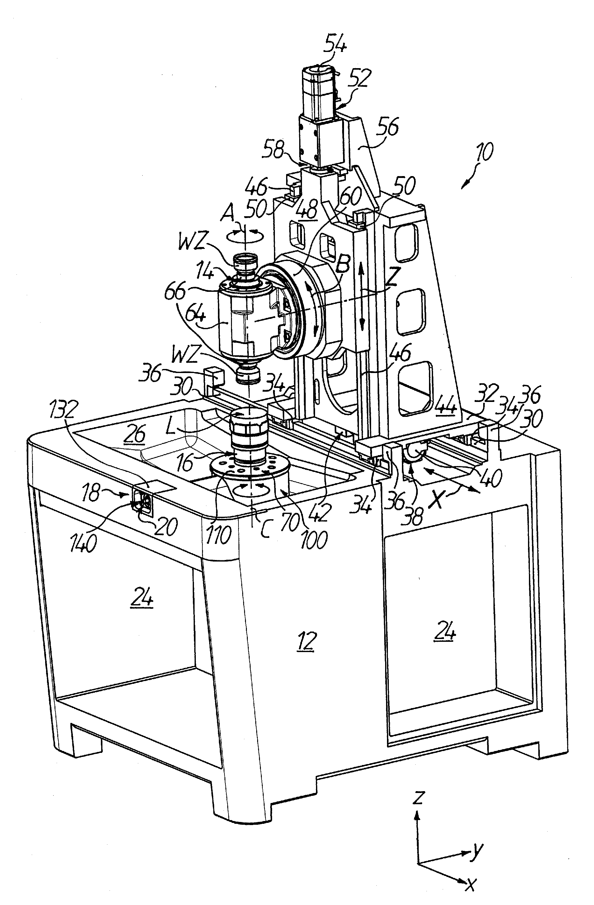
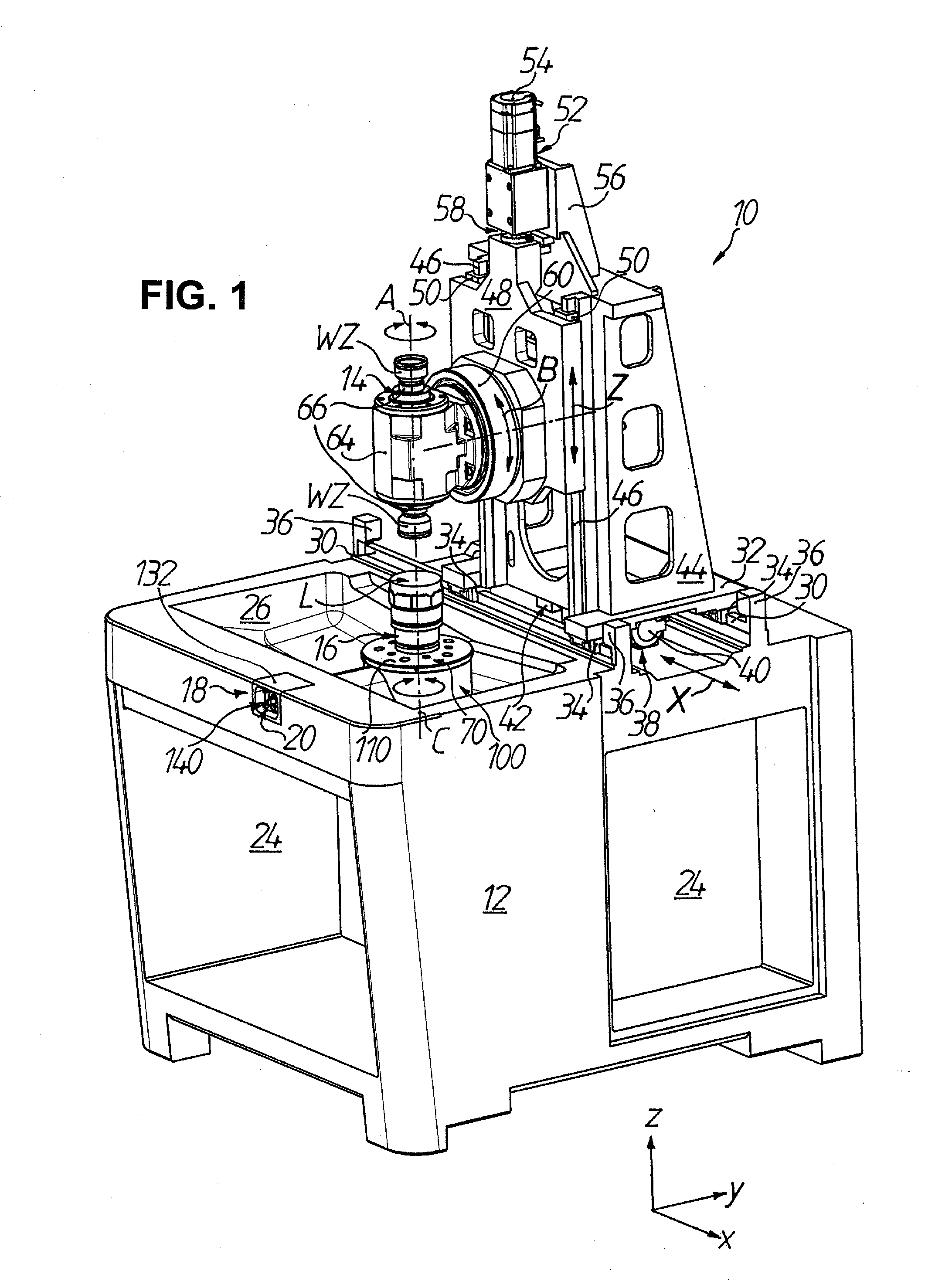
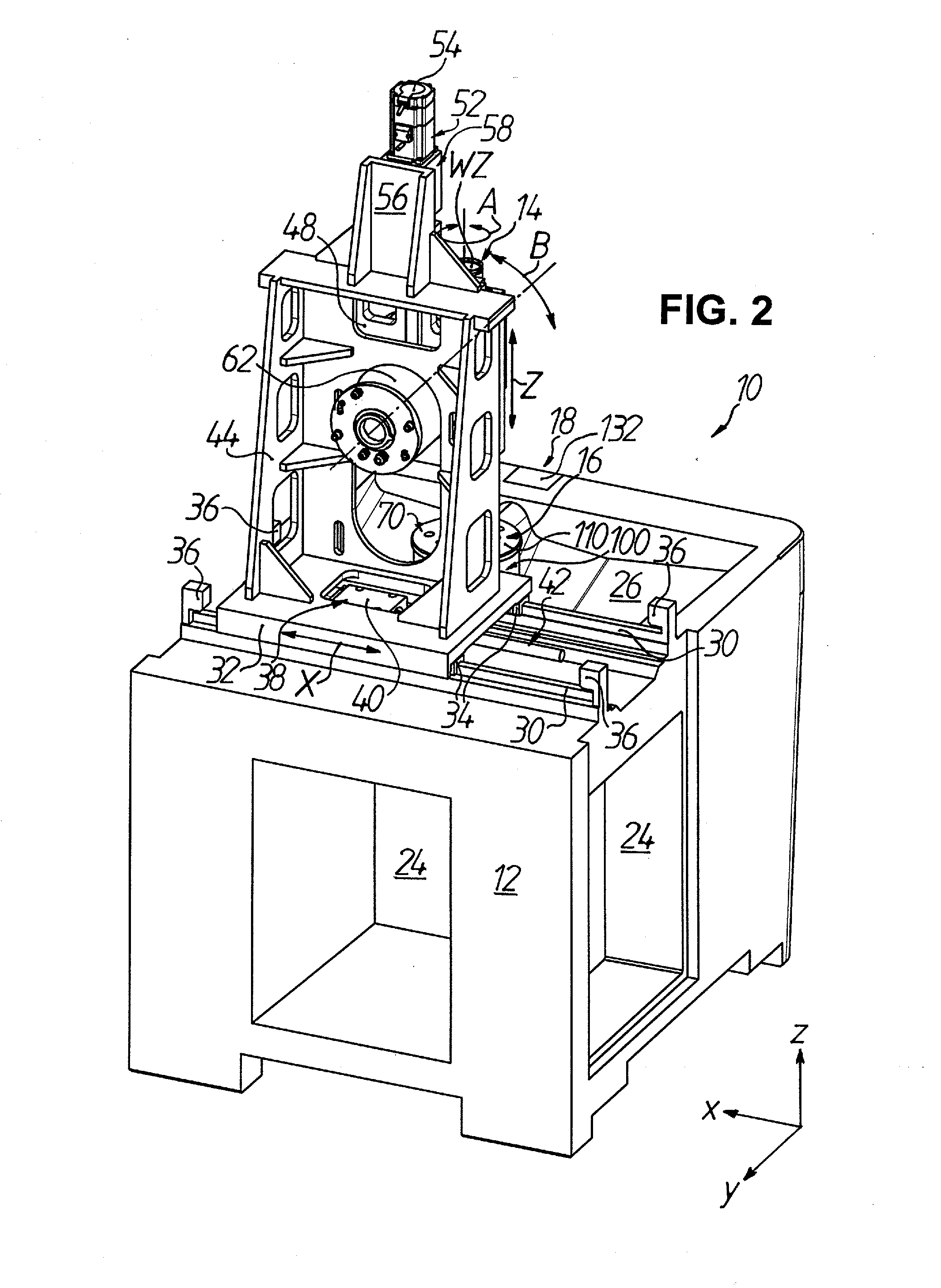
[0038]FIGS. 1 to 4 show in partly schematic illustration a CNC-controlled device 10 for grinding, fine precision-grinding and / or polishing of workpieces in optical quality, particularly of spherical surfaces at lenses L in precision optics, in a right-angled Cartesian co-ordinate system in which the lower-case letters x, y and z respectively denote the width direction (x), length direction (y) and height direction (z) of the device 10.

[0039]The device 10 generally comprises a machine frame 12, which cast monolithically from a polymer concrete forms at the same time a machine bed, an upper tool spindle 14, by which at least one tool WZ, in the illustrated embodiment, two tools WZ mounted at opposite ends of the tool spindle 14 is drivable for rotation about a tool axis A of rotation, and a lower workpiece spindle 16, by which the workpiece, i.e. here the lens L, is drivable for rotation about a workpiece axis C of rotation. In this regard, as characterized in the figures by movement ...


PUM

PropertyMeasurementUnit
pressureaaaaaaaaaa
circumferenceaaaaaaaaaa
shapeaaaaaaaaaa

Abstract

A device for grinding and/or polishing of, in particular, precision-optical spherical lens surfaces has a machine frame, a tool spindle for rotational drive of a tool about a tool axis of rotation and a workpiece spindle for rotational drive of a workpiece about a workpiece axis of rotation. The tool spindle and workpiece spindle are capable of axial relative adjustment in first and second directions extending perpendicularly to one another and in addition pivotable about a pivot axis in a pivot plane relative to one another. Equipment for cross-grinding adjustment is provided, which has an adjusting mechanism to position the workpiece spindle in a third direction extending perpendicularly to the first and second directions. A clamping mechanism activatable independently of the adjusting mechanism serves the purpose of fixing the workpiece spindle, once positioned, with respect to the machine frame.

Description

TECHNICAL FIELD[0001]The present invention relates to a device for grinding, precision-grinding and / or polishing of workpieces in optical quality. In particular, the invention relates to a device for grinding, precision-grinding and / or polishing of spherical lens surfaces that are mass-processed in precision optics.PRIOR ART[0002]In the processing or precision-processing discussed here, for which as grinding tools use is made of, in particular, cup grinding wheels or combination grinding wheels (for example according to German standards DIN 58741-2, DIN 58721-4, DIN 58721-5, DIN 58721-6 or DIN 58721-7) or precision-grinding or polishing tools (for example polishing bowls), the tool and the workpiece rotate in the same or opposite direction and are at the same time pivoted relative to one another, so that the zone of engagement between the tool and the workpiece constantly changes.[0003]For, in particular, dressing of a spherical polishing tool at a polishing machine and for grinding...

Claims


Application Information

Patent Timeline
Patent Type & Authority Applications(United States)
IPC IPC(8): B24B11/00B24B13/01
CPCB24B13/01B24B11/00B24B13/06
Inventor BECKER, BENJAMINDIEHL, JOACHIMSTROH, CARSTENZEUKE, ROBERT
Owner SATISLOH AG
Why Eureka
Try Eureka