Stationary co-axial multi-rotor wind turbine supported by continuous central driveshaft
a coaxial, wind turbine technology, applied in the direction of machines/engines, renewable energy generation, greenhouse gas reduction, etc., to achieve the effect of less required stiffness, less cost, and less required stiffness
- Summary
- Abstract
- Description
- Claims
- Application Information
AI Technical Summary
Benefits of technology
Problems solved by technology
Method used
Image
Examples
eighth embodiment
8. Eighth Embodiment
Catenary Co-Axial, Multi-Rotor Turbine Suspended Between Multiple Towers; FIGS. 10 and 11
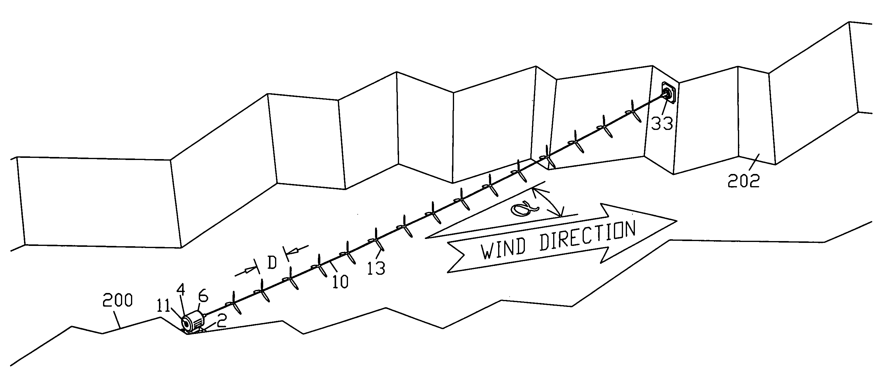
[0201]The eighth embodiment is similar to the seventh, with the addition of one or more intermediate supports 220, in this case taking the form of towers 90, stabilized by guy wires 55, supporting bearings 11 to help elevate the driveshaft as in the second embodiment. The intermediate supports allow a longer driveshaft, to support more rotors, thereby increasing swept area and hence increasing power output. Alternatively such intermediate supports may be used in lieu of driveshaft tension and / or stiffness, to whatever extent is appropriate for a given installation, as simply an alternate method of supporting the driveshaft over its length. The generator may be located proximate the upwind end of the driveshaft, as in the seventh embodiment of FIG. 9, at the downwind end, or at an intermediate location, as shown in FIGS. 10 and 11. Placing the generator at the upwind end of th...
ninth embodiment
9. Ninth Embodiment
Horizontal Planar Array of Stationary Co-Axial Multi-Rotor Turbines; FIGS. 12 and 13
[0202]Multiple turbines of the seventh or eighth embodiment may be installed side-by-side. Horizontal guy wires between units 57 may be used to help support all but the peripheral towers of the array, preserving the space below the array for other uses without the intrusion of guy wires. An example would be a parking lot below the turbines, in which case the towers could also serve as supports for the parking lot lights. Another example would be farming. Spacing between turbines should be sufficient to allow fresh wind to reach each line of rotors. This grid of turbines sharing horizontal guy wires 57 of FIG. 12 is similar to the 31st embodiment of U.S. Pat. No. 6,616,402, illustrated in FIG. 42 of that patent, issued to this inventor. Alternatively, freestanding towers of sufficient strength may require no guy wires as in FIG. 13.
tenth embodiment
10. Tenth Embodiment
Vertical Planar Array of Stationary Co-Axial Multi-Rotor Turbines; (“Windfence”) FIG. 14
[0203]Multiple turbines of the seventh or eighth embodiment may be stacked in a vertical array, sharing the same towers, forming a virtual wall of rotors similar to that of the third embodiment. Rotors of adjacent driveshafts may be staggered to allow closer spacing as in the fourth embodiment. Such towers may or may not require guy wires, depending on construction. A multiplicity of such vertical arrays may be placed side-by-side (illustrated), in which case sufficient spacing should be provided to allow fresh wind to reach each turbine array.
PUM
 Abstract
Description
Claims
Application Information
 - R&D
- Intellectual Property
- Life Sciences
- Materials
- Tech Scout
- Unparalleled Data Quality
- Higher Quality Content
- 60% Fewer Hallucinations
Browse by: Latest US Patents, China's latest patents, Technical Efficacy Thesaurus, Application Domain, Technology Topic, Popular Technical Reports.
© 2025 PatSnap. All rights reserved.Legal|Privacy policy|Modern Slavery Act Transparency Statement|Sitemap|About US| Contact US: help@patsnap.com


