Anchor tendon with selectively deformable portions

a technology of anchor tendon and selective deformation, which is applied in the direction of fastening means, dowels, mining structures, etc., can solve the problems of tendon deformation, increased risk of premature failure, and rupture and resin mixing, so as to increase the height and/or depth of the bar deformation, increase the bar stiffness and rigidity, and reduce the deformation range

Active Publication Date: 2013-01-31
DSI UNDERGROUND CANADA LTD SOUTERRAIN DSI CANADA LTEE
View PDF2 Cites 12 Cited by
  • Summary
  • Abstract
  • Description
  • Claims
  • Application Information

AI Technical Summary

Benefits of technology

[0008]According to one aspect of the invention, deformations are selectively formed on selected surfaces of an anchor rod or bolt. The deformations are created having varying heights, spacing and dimensions over selective sections to control the anchor stiffness along a given section of the anchor tendon and provide selected sections of the tendon with the ability to preferentially plastically deform and/or elongate ahead of others. In particular, the applicant has appreciated that increasing the height and/or depth of th...

Problems solved by technology

Following resin cartridge placement, the anchor tendon is slid axially into the bore hole and driven through the cartridges resulting in their rupture and resin mixing.
The applicant has appreciated that in fully grouted bolt installations, where the anchor tendon is substantially encapsulated along its entire axial length to a distance of 50 cm or less, and typically within about 25 cm or less from the rock face, the tendon maybe subject to an increased chance of premature failure as a result of differential ground movement.
Typically, the failure of the tendon results from the overall bar stiffness and the inability of the tendon to plastically deform.
When an anchor bolt fractures or breaks across its threaded end, any connection with mesh screens or other surface retention elements used to capture falling rock and debris is ...

Method used


Image

  • Anchor tendon with selectively deformable portions
  • Anchor tendon with selectively deformable portions
  • Anchor tendon with selectively deformable portions

Examples


Embodiment Construction

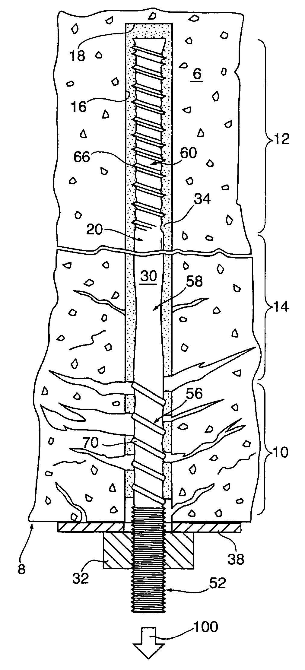
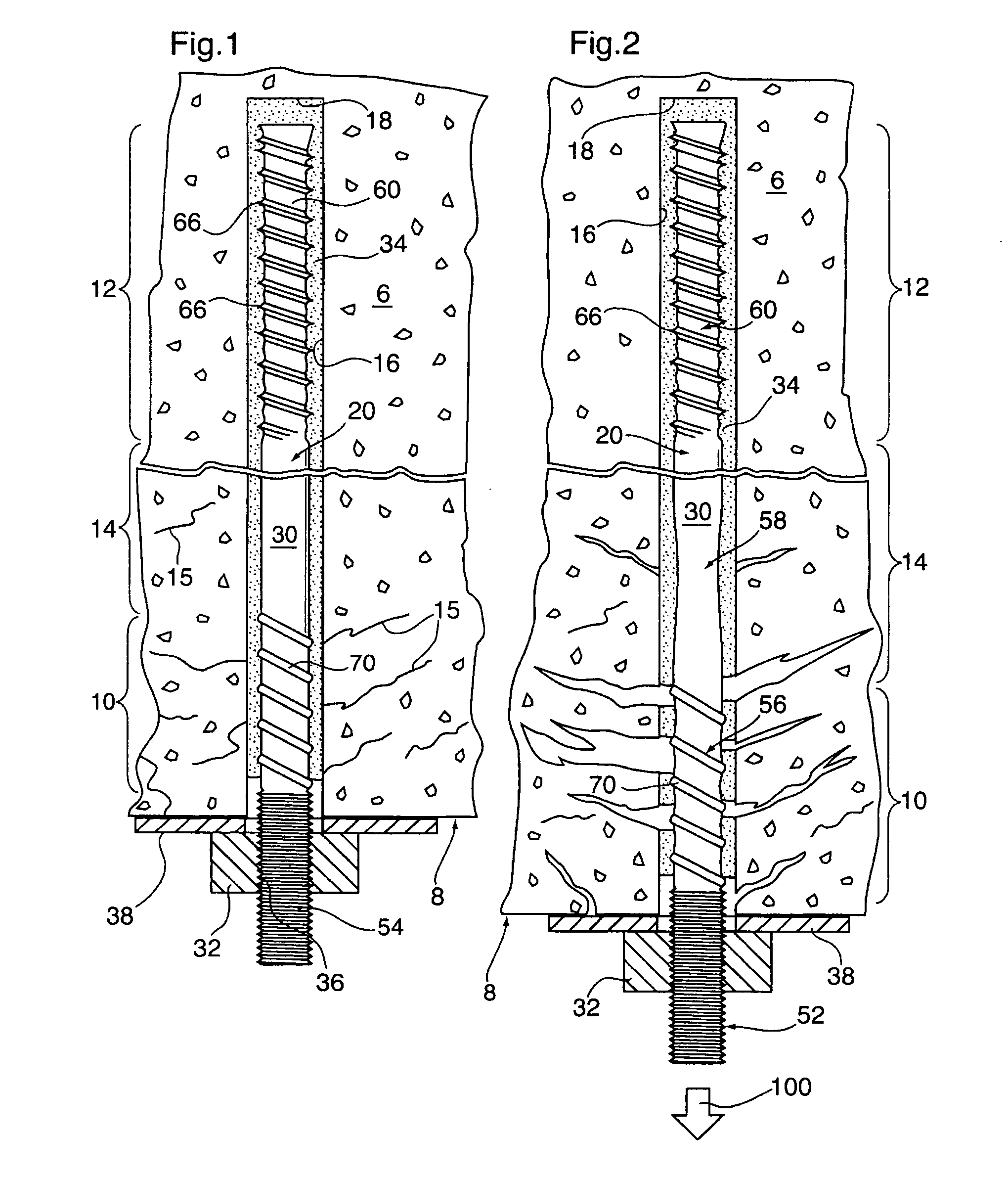
[0031]FIGS. 1 and 2 illustrate a typical rock complex 6 where a rock face 8 is exposed by blasting. As a result of blasting forces, the rock complex 6 most typically includes a fractured rock zone 10 which is immediately adjacent to the rock face 8, a cohesive rock zone 12, and a transition rock zone 14 intermediate the fractured zone 10 and the cohesive zone 12. The fractured rock zone 10 extends inwardly a distance of approximately between about 0.25 and 0.75 metres from the rock face 8. The fractured zone 10 is most typically characterized by a series of micro-fractures 15 which are produced by the blasting forces. In hard rock applications, the cohesive zone 12 most often consists of unfractured rock strata, with the transition zone 14 consisting substantially of unfractured rock with a few micro-fracture 15.

[0032]The present invention relates to a mine roof support system 20 which, as shown best in FIGS. 1 and 2, is adapted not only for the static reinforcement and consolidatio...


PUM


Abstract

A mine roof support system includes an elongated anchor rod or tendon having a rigid non-deformable distalmost anchoring end portion, and one or more axially deformable portions which are configured to deform in the event load forces exceed a threshold force approximating the forces during a rock burst or rock dilation event. The rigid anchoring portion is provided with primary anchor members such as ribs, gooves, studs and the like. The primary anchor members are configured to reduce bar plasticity, and fixedly secure and retain the rigid portion in place in a drill hole. In the event rock forces exceed the threshold force, the plastically deformable portions elongate with the dilating rock to accommodate and absorb the rock forces.

Description

SCOPE OF THE INVENTION[0001]The present invention relates to a retaining wall or mine roof bolt assembly, and more particularly, a bolt assembly which includes a reinforcing anchor bolt or tendon having one or more selectively deformable portions. The deformable portions are configured to preferentially plastically deform and / or axially elongate in response to ground or load forces which exceed a predetermined threshold force, to assist in the absorption and dissipation of load forces.BACKGROUND OF THE INVENTION[0002]In conventional mine roof and wall support systems (hereinafter collectively referred to as “mine roof support systems”) a threaded rod-like reinforcing tendon or rebar is imbedded into a bore or drill hole which is drilled into a rock complex. Depending upon the diameter of bar stock used, conventional anchor tendons are generally installed in bore holes which range in diameter from about 25 to 50 mm. Conventional reinforcing tendons are provided with a threaded proxim...

Claims


Application Information

Patent Timeline
IPC IPC(8): E21D20/00E21D21/00
CPCE21D21/004F16B13/141E21D21/02
Inventor CHAMPAIGNE, DENISCAI, MING
Owner DSI UNDERGROUND CANADA LTD SOUTERRAIN DSI CANADA LTEE
Why Eureka
Try Eureka