Ice protection system

Active Publication Date: 2005-02-01
SHORT BROTHERS
View PDF14 Cites 51 Cited by
  • Summary
  • Abstract
  • Description
  • Claims
  • Application Information

AI Technical Summary

Benefits of technology

To retrofit the ice protection system according to the invention to replace a conventional ice protection system, hot air at the same mass flow rate but lower temperature could be used, or alternatively a lower mass flow rate at the same temperature could be used. The latter option is more desirable because the same source of hot air, such as an engine compressor bleed port, could be used and the throat area of a flow-limiting venturi could

Problems solved by technology

If the water is not completely evaporated it will run back along the aircraft skin surface and may then freeze and accumulate on a part of the surface that is not heated.
There is a danger that the ice so formed will adversely affect the aircraft's efficiency and handling qualities.
In addition, any accumulated ice on the aircra

Method used


Image

  • Ice protection system
  • Ice protection system
  • Ice protection system

Examples


Example

While the invention is susceptible to various modifications and alternative forms, specific embodiments thereof are shown by way of example in the drawings and will herein be described in detail. It should be understood, however, that there is no intent to limit the invention to the particular forms disclosed, but on the contrary, the invention is to cover all modifications, equivalents, and alternatives falling within the spirit and scope of the invention as defined by the claims. Like numbers refer to like elements throughout the description of the figures. Although described herein primarily with respect to protecting aircraft structures from the accumulation of ice thereon, it will be understood that ice protection system and method embodiments of the present invention may also be used with other structures without departing from the principles of the present invention.

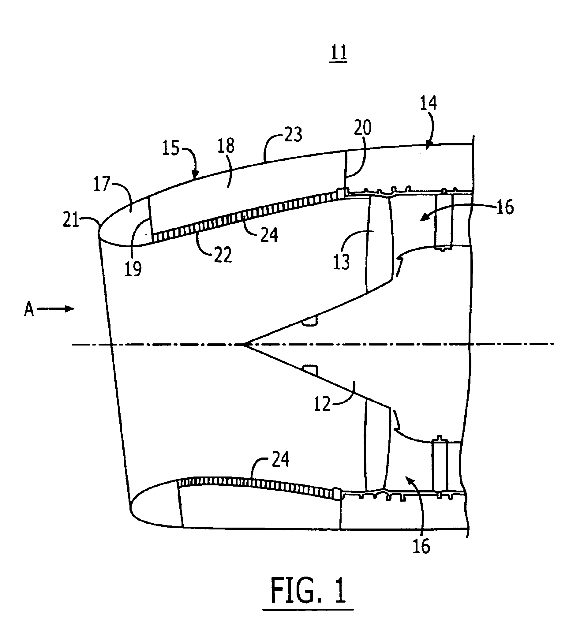
Referring to the drawings and initially to FIG. 1 thereof, a forward part of an aircraft engine 11 is shown com...


PUM


Abstract

An aircraft engine nacelle nose cowl has a supply duct to deliver pressurised hot gas into an internal compartment of the nose cowl. A slot is provided in the nose cowl to enable pressurised hot gas to pass out of the compartment through the slot. As the pressurised hot gas passes out of the compartment through the slot, this causes a film of water on an outer surface of the nose cowl to detach from the nose cowl. The slot is of restricted dimensions which causes localised heating of the nose cowl around the slot as the pressurised hot gas pass out of the compartment through the slot. In this manner ice is prevented from accumulating on the outer surface of the nose cowl and/or ice is removed from the outer surface of the nose cowl.

Description

RELATED APPLICATIONThis application claims priority to Great Britain Patent Application No. GB0211800.8, filed May 22, 2002, the disclosure of which is hereby incorporated herein by reference.FIELD OF THE INVENTIONThis invention relates to an ice protection system suitable for use with aircraft structures. In particular, this invention is concerned with, but not exclusively limited to, an ice protection system for use with an aircraft engine nacelle nose cowl.BACKGROUND TO THE INVENTIONSome aircraft surfaces require to be protected from the accumulation of ice caused by the collection and freezing of ambient moisture. Ice protection is frequently achieved by heating the aircraft skin so that the water catch on the skin is prevented from freezing and is partially or completely evaporated. If the water is not completely evaporated it will run back along the aircraft skin surface and may then freeze and accumulate on a part of the surface that is not heated. There is a danger that the ...

Claims


Application Information

Patent Timeline
IPC IPC(8): B64D33/02B64D15/00B64D33/00B64D15/04
CPCB64D15/04B64D33/02B64D2033/0233B64D2033/0206
Inventor LINTON, ALAN
Owner SHORT BROTHERS
Why Eureka
Try Eureka