Radial compressor, particularly for an exhaust gas turbocharger of an internal combustion engine

a technology of internal combustion engine and compressor, which is applied in the direction of machines/engines, stators, liquid fuel engines, etc., can solve the problems of instabilities in compressor operation, damage to the radial compressor, and corresponding efficiency loss, so as to improve the degree of asymmetry and simplify the inflow behavior

Inactive Publication Date: 2013-09-03
IHI CHARGING SYST INT
View PDF11 Cites 13 Cited by
  • Summary
  • Abstract
  • Description
  • Claims
  • Application Information

AI Technical Summary

Benefits of technology

[0008]In other words, it is provided that the compressor housing has, in contrast to the state of the art, a geometry deviating from the symmetry with respect to the compressor axis in its regions upstream of the usually spirally and thus asymmetrically formed outlet channel. Hereby, a defined flow irregularity and a correspondingly asymmetric inflow and outflow of the compressor wheel can be provided, whereby, surprisingly, a significant stabilization of the rotational flow discontinuity is achieved in the different flow channels of the compressor housing and the pumping tendency of the compressor wheel is displaced to significantly lower mass flow rates. Due to this constructively simple measure, an improved and in particular cost-efficient adaptability of the radial compressor to requirement profiles of different types of internal combustion engines is additionally obtained.
[0017]In a further advantageous arrangement of the invention, several stays are provided which are preferably formed in an asymmetric manner with regard to the rotational axis over the circumference of the channel wall. In this manner, larger circumferential regions can be covered with material in a defined manner, whereby a correspondingly increased degree of asymmetry can be achieved. A mechanically stable support of the channel wall in the compressor housing is achieved with the help of several stays.

Problems solved by technology

In addition, there is the danger that during an operation below the surge line the radial compressor is damaged already after a relatively short running time.
The possiblity that flow swirls and flow displacements form during an operation near the surge line in the region of the rotating compressor wheel is thereby seen to be disadvantageous with the known radial compressors, as this leads to corresponding efficiency losses and instabilities in the compressor operation.

Method used


Image

  • Radial compressor, particularly for an exhaust gas turbocharger of an internal combustion engine
  • Radial compressor, particularly for an exhaust gas turbocharger of an internal combustion engine

Examples


Embodiment Construction

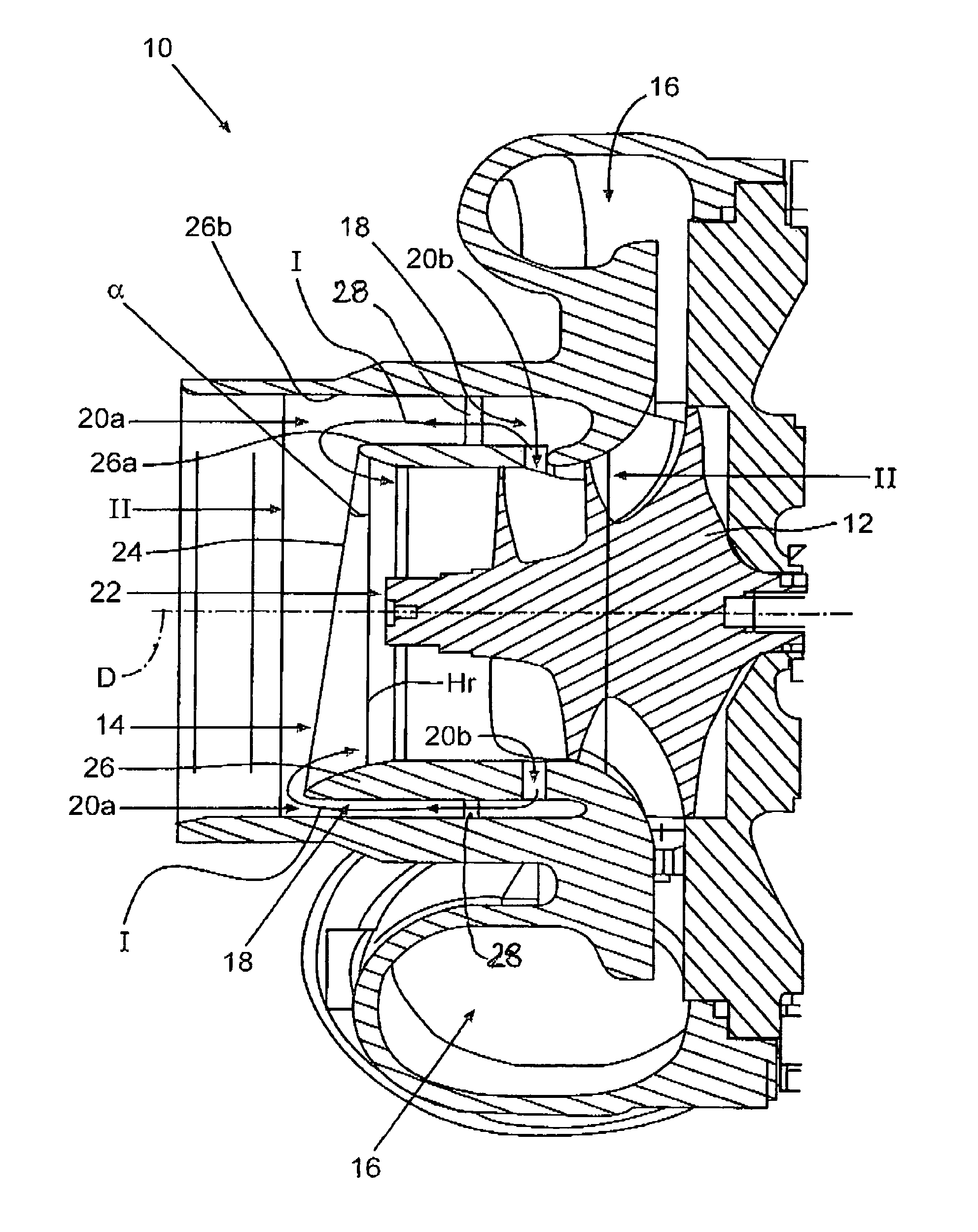
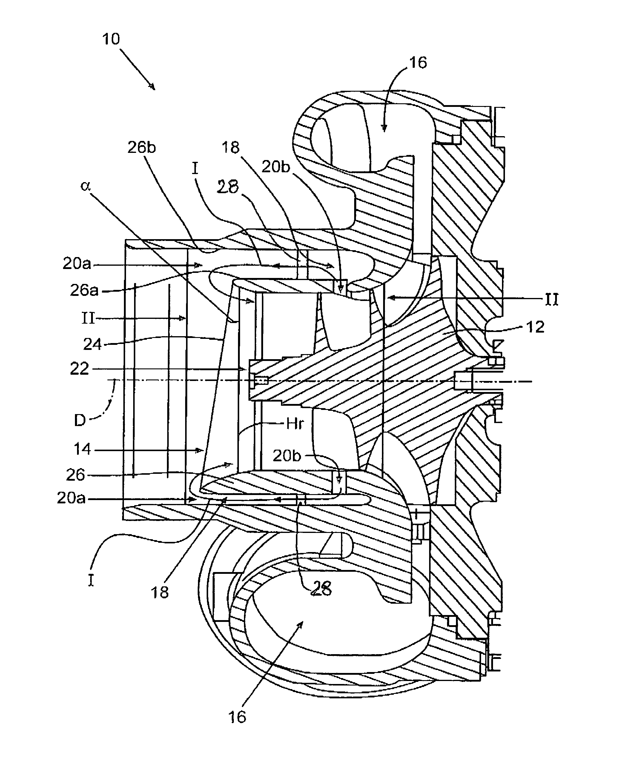
[0021]FIG. 1 shows a schematic lateral sectional view of a radial compressor according to one embodiment of the invention. The radial compressor, which is in the form of a compressor of an exhaust gas turbocharger, comprises a compressor housing 10, in which a compressor wheel 12 is arranged. With the help of the compressor wheel 12, air from an inflow channel 14 of the compressor housing 10 is compressed and directed into a spiral outflow channel 16 of the compressor housing 10. The compressor wheel 12 is driven in a manner known per se via a turbine wheel (not shown) of a turbine of the exhaust gas turbocharger. The compressor housing 10 additionally comprises an annular bypass channel 18, which has at least a first flow opening 20a arranged upstream of an axial compressor wheel inlet 22 to the compressor wheel 12 and a second flow opening 20b arranged downstream of the compressor wheel inlet 22. In an operating region near the surge line, it is possible with the KSM performance g...


PUM


Abstract

In a radial compressor, particularly of an exhaust gas turbocharger of an internal combustion engine, having a compressor housing within which a compressor wheel is disposed for compressing air from an inflow channel of the compressor housing and directing the air to an outflow channel of the compressor housing, the compressor housing comprising a bypass channel having a first flow opening upstream of an axial compressor wheel inlet and a second flow opening downstream of the compressor wheel inlet, the compressor housing is configured at least in a flow region upstream of the second flow opening in an asymmetric manner with regard to a rotational axis of the compressor wheel.

Description

[0001]This is a Continuation-In-Part Application of pending international patent application PCT / EP2009 / 006387 filed Sep. 3, 2009 and claiming the priority of German patent application 10 2008 047 506.8 filed Sep. 17, 2008.BACKGROUND OF THE INVENTION[0002]The invention relates to a radial compressor, particularly for an exhaust gas turbocharger of an internal combustion engine and also to a motor vehicle with an internal combustion engine and a turbocharger having a radial compressor arranged in an intake section of the internal combustion engine.[0003]The development of charged internal combustion engines for utility or passenger motor vehicles with a desired torque behavior require increasingly broadened compressor characteristic fields. The compressor characteristic field, in which the relation of the starting pressure to the input pressure of the compressor is plotted with regard to the mass flow rate, is limited on the one side by the so-called surge line of the compressor, tha...

Claims


Application Information

Patent Timeline
Patent Type & Authority Patents(United States)
IPC IPC(8): F01D1/12F02B33/44F04D29/44
CPCF04D29/4206F04D27/0207F04D29/4213F04D29/685F05D2220/40
Inventor SUMSER, SIEGFRIEDKRATSCHMER, STEPHANSTILLER, MICHAEL
Owner IHI CHARGING SYST INT
Why Eureka
Try Eureka