Method and control system for applying defined clamping forces

a control system and clamping force technology, applied in the direction of braking systems, braking components, transportation and packaging, etc., can solve the problem of indication of how defined clamping force can be applied, and achieve the effect of reducing the time necessary and improving the control quality

Inactive Publication Date: 2005-02-01
CONTINENTAL TEVES AG & CO OHG
View PDF9 Cites 10 Cited by
  • Summary
  • Abstract
  • Description
  • Claims
  • Application Information

AI Technical Summary

Benefits of technology

Therefore, an object of the present invention is to disclose a method and a control system permitting a reduction of the time necessary for the initialization of the sensors. To this end, it is appreciated for the actuator position to be determined in which the brake linings are just abutting on the brake disc, however, with brake force not yet transmitted at this moment. Another objective is to improve the control quality by taking the non-linear characteristic of rigidity into consideration.
With the parameters of the polynomial available, the functioning of the clamping force sensor can be tested in a simple fashion. To this end, e.g. the difference between the current clamping force sensor value and the clamping force value which results from the evaluation of the polynomial for the current actuator position is calculated, and the amount is checked with respect to a threshold value. If this difference exceeds the predefined threshold value, this indicates a defective clamping force sensor.

Problems solved by technology

The above-mentioned publication, however, does not provide any indication about how defined clamping forces can be applied in the operation of the state of the art brake.
Further, the control concept does not take the non-linear characteristic curve of rigidity of the system into account.

Method used


Image

  • Method and control system for applying defined clamping forces
  • Method and control system for applying defined clamping forces
  • Method and control system for applying defined clamping forces

Examples


Embodiment Construction

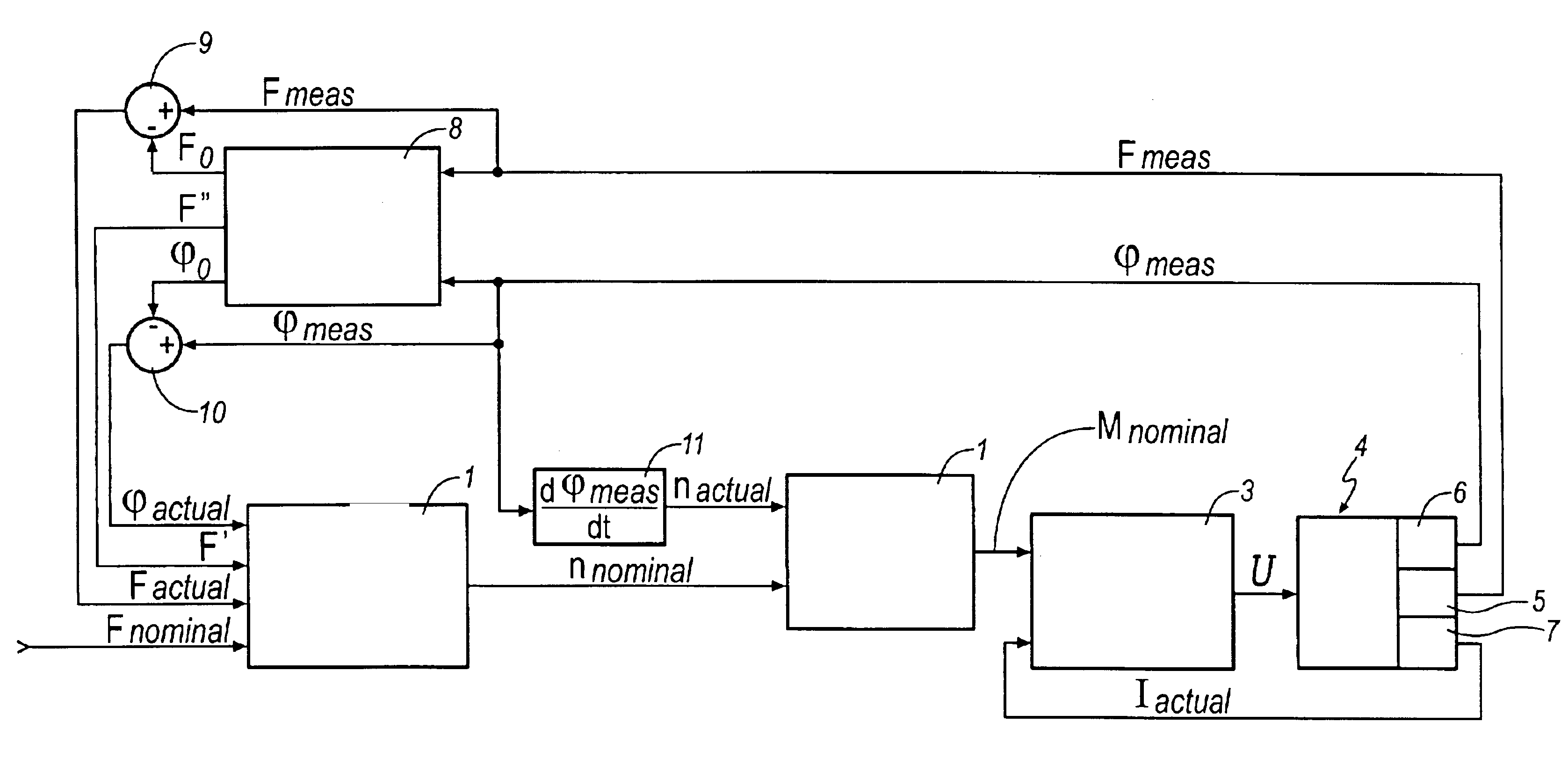
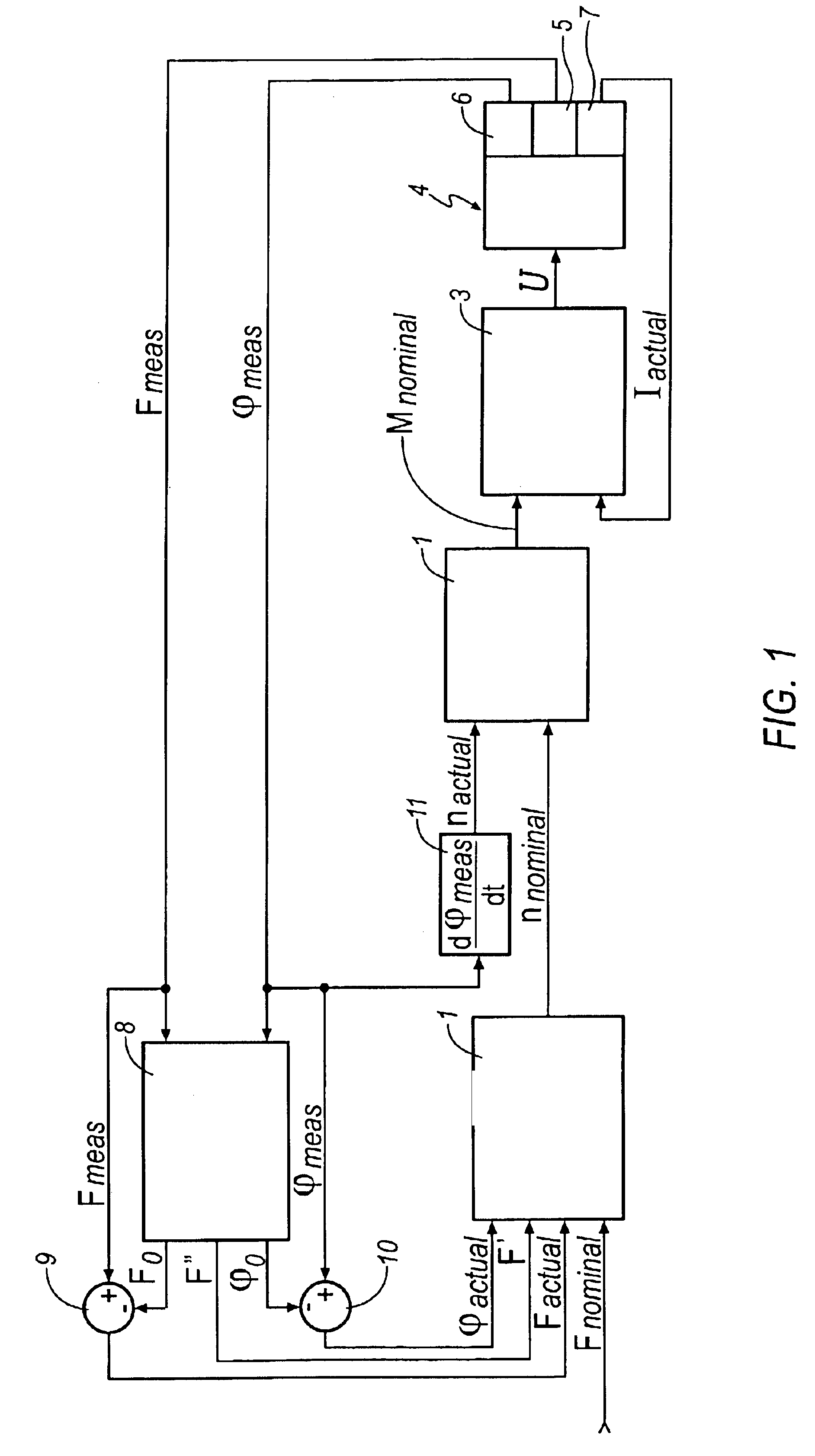
The control system illustrated in FIG. 1 is generally comprised of a first controller or force / travel controller 1, a characteristic curve identification module 8 connected upstream of the force / travel controller 1, a second controller or speed controller 2 connected downstream of the force / travel controller 1, as well as a third controller or current controller 3 connected downstream of the speed controller 2, with an integrated servo booster generating a voltage U that is applied to an actuator 4 (only represented) of an electromechanically operable brake. The actuator 4 is preferably equipped with a clamping force sensor 5, a position measuring system 6 and a current sensor 7, with an output signal Fmeas of the clamping force sensor 5 representative of the measured clamping force being sent as a first input quantity to the characteristic curve identification module 8 and an output signal φmeas of the position measuring system 6 representative of the measured actuator position bei...


PUM


Abstract

A method and a control system for applying defined clamping forces in a brake that is electrically operable by an actuator and includes a first friction surface and a second friction surface in between which a clearance is allowed, wherein the application the first friction surface against the second friction surface is determined, and wherein a static correlation exists between its actuating travel or, respectively, the actuator position and clamping force, and wherein values of the clamping force as well as of the actuator position measured by a clamping force sensor and a position sensor are determined. To optimize the time-consuming initialization of the sensors used to determine the clamping force and the actuator position and, respectively, to take into account the non-linear rigidity characteristic of the system the control concept, the present invention discloses having the correlation described by a mathematical model whose parameters are determined during actuation.

Description

TECHNICAL FIELDThe present invention generally relates to a method and a control system for applying defined clamping forces in a brake and more particularly relates a method and a control system for applying defined clamping forces in a electrically operable brake for automotive vehicles.BACKGROUND OF THE INVENTIONInternational patent application WO 96 / 033010 discloses a disc brake that is preferably operable by means of an electric motor by way of a reducing gear system. The special features of the prior art brake involve that the rotor of the electric motor has an annular design and embraces the reducing gear system in a radial way. These measures allow considerably shortening the axial overall length of the actuating unit. The above-mentioned publication, however, does not provide any indication about how defined clamping forces can be applied in the operation of the state of the art brake.The publication ‘Electromechanical Brake System: Actuator Control Development Systems’, SA...

Claims


Application Information

Patent Timeline
Patent Type & Authority Patents(United States)
IPC IPC(8): B60T13/74B60T13/00
CPCB60T13/741
Inventor MARON, CHRISTOFWIEHOFF, HANS-JORG
Owner CONTINENTAL TEVES AG & CO OHG
Why Eureka
Try Eureka