
Grease separator for kitchen sinks and other applications

a technology for separating grease and kitchen sinks, which is applied in the direction of feeding/discharge of settling tanks, machines/engines, and settling tanks, etc., can solve the problems of oil and grease put into the sewer system by food processing facilities, clogging of sewer system lines, and difficulty in servicing the apparatus, etc., to achieve easy maintenance, low cost, and easy installation

Active Publication Date: 2005-02-01
THERMACO INC
View PDF14 Cites 30 Cited by
  • Summary
  • Abstract
  • Description
  • Claims
  • Application Information

AI Technical Summary

Benefits of technology

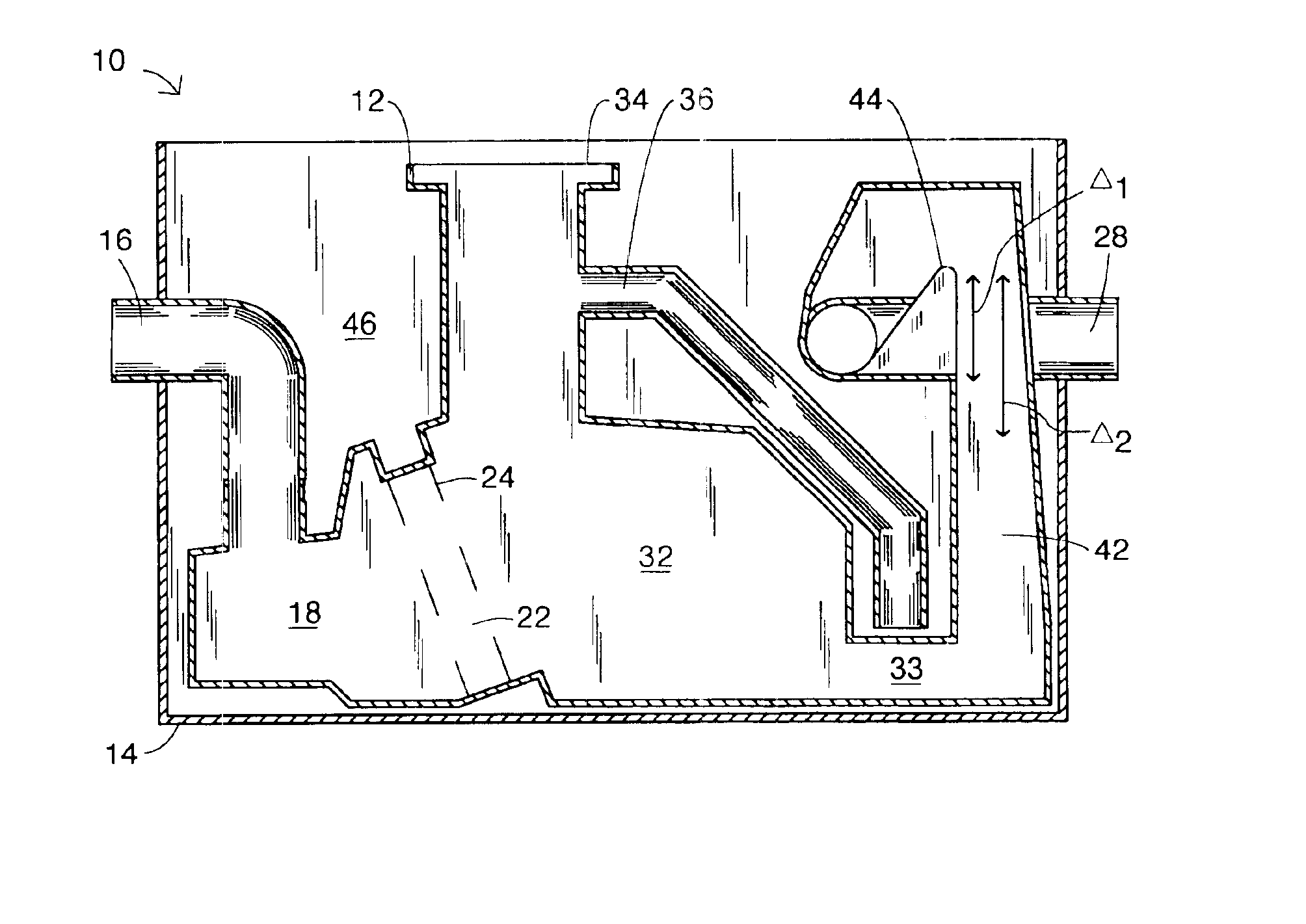
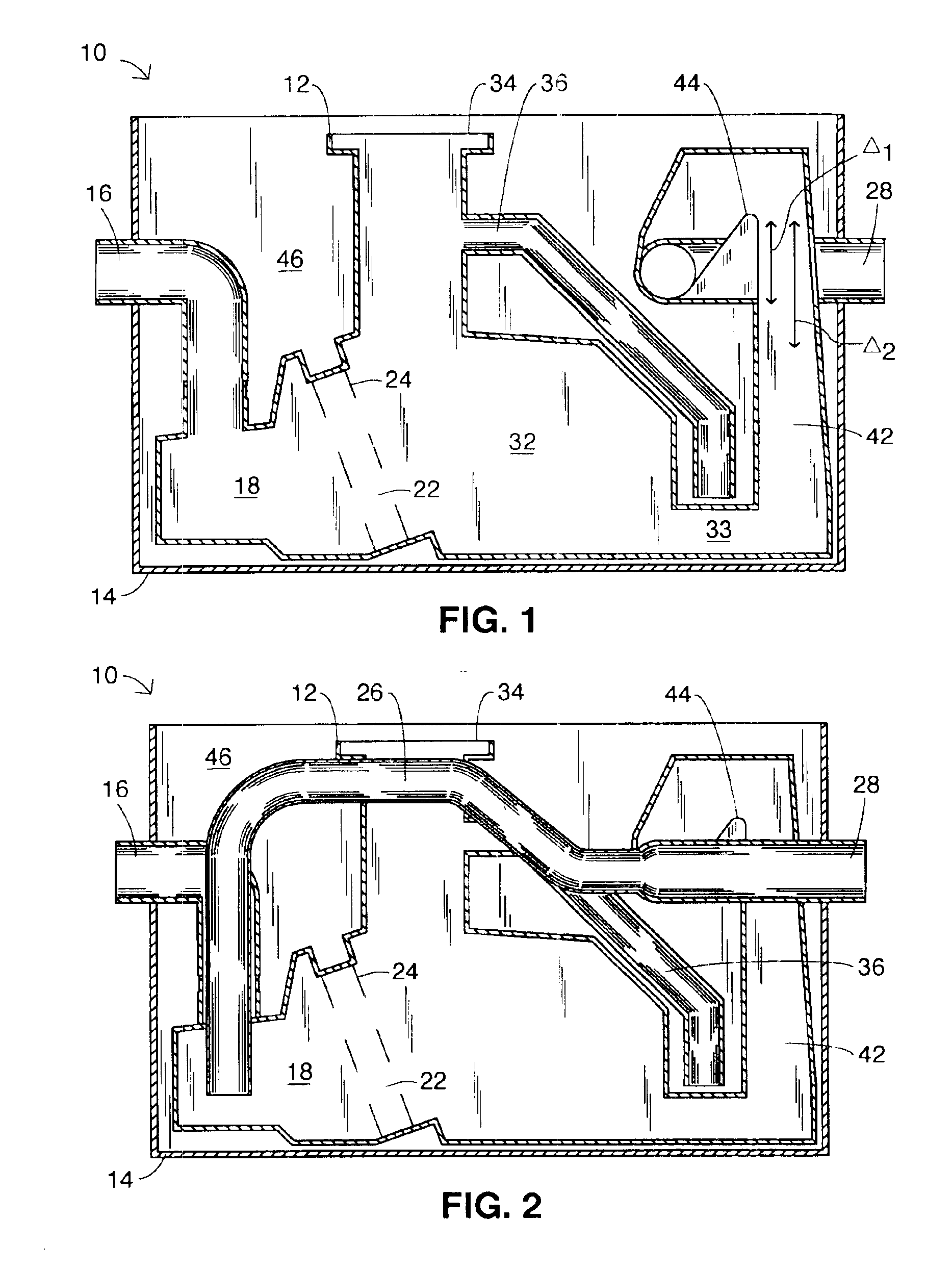
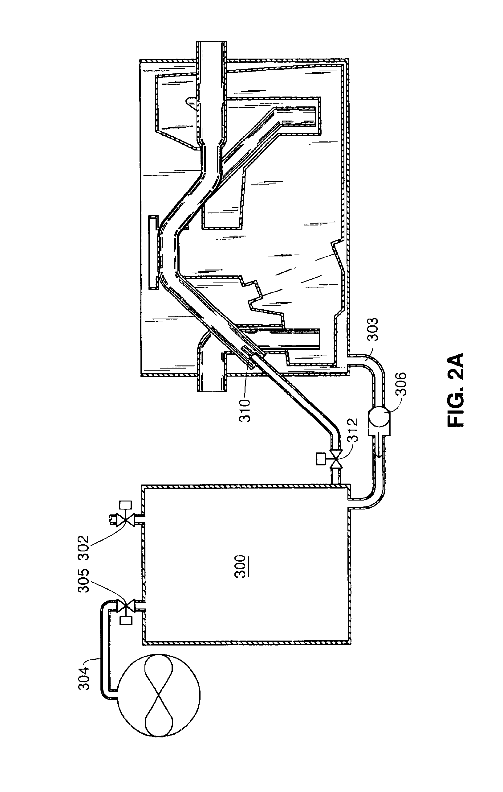
The present invention fulfills one or more of these needs in the art by providing an oil / grease and solid waste removal apparatus which is low in cost, easy to maintain and easy to install. The apparatus isolates lighter liquid from a mixture of the heavier liquid and a lighter liquid with which the lighter liquid is immiscible. A housing has an inner volume with an inlet into the volume to receive an influent flow of a mixture of the heavier liquid and the lighter liquid. A first outlet from the volume to discharge the heavier liquid is positioned such that the first outlet defines a static liquid level in the housing and a second outlet is positioned in the housing so substantially all of the lighter liquid held in the volume can flow through the second outlet, which may be above the static liquid level in the housing. As surges of influent flow are received in the housing and temporarily raise the liquid level above the static liquid level, lighter liquid on top of the heavier liquid in the volume is discharged through the second outlet, together with portions of the heavier liquid. A storage vessel receives the liquids from the second outlet. The second outlet may act as a return path from a low portion of the storage vessel to the housing to return heavier liquid from the storage vessel to the housing. The lighter liquid in the housing tends to float on the heavier liquid in the housing, so that transient large volume flows into the inlet of the housing have minimal tendencies to disturb the lighter liquid and therefore do not cause a substantial discharge of the lighter liquid with the heavier liquid through the first outlet.
In a preferred embodiment, an outer tank serves as the storage vessel. An inner tank has the inlet, which discharges downwardly into the inner tank. The inner tank is preferably made of roto-molded plastic and has multiple chambers with varying heights from the inlet to the first outlet. The multiple chambers of the inner tank promote a rise and fall of liquid within the inner tank caused by large volume flows when the connected sink is emptied. This flow of fluids aids the oil and grease to rise to the top of a liquid column within a chamber of the inner tank.

Problems solved by technology

One of the largest problems, in terms of sewer system lines clogging, has been the oils and grease put into the sewer system from food handling facilities.
This makes servicing of the apparatus difficult, particularly since the parts to be serviced have been covered in grease and oil.
Because of the nature of installation, the field service is difficult.

Method used


Image

  • Grease separator for kitchen sinks and other applications
  • Grease separator for kitchen sinks and other applications
  • Grease separator for kitchen sinks and other applications

Examples


Embodiment Construction

In the following description, like reference characters designate like or corresponding parts throughout the several figures. It should be understood that the illustrations are for the purpose of describing preferred embodiments of the invention and are not intended to limit the invention thereto.

As best seen in FIGS. 1 through 3, an embodiment of the oil / grease separator 10 includes an inner tank 12, an outer tank 14, an inlet 16 and an outlet 28. The oil / grease separator 10 is typically connected to a sink (not shown). However, other sources of effluent such as machine tools or the like can also be serviced. Together, these sources are referred to herein as “sinks.” The sink drain is connected to the inlet 16 and discharges downwardly into the inner tank 12. The inner tank 12 is preferably made of roto-molded plastic and comprises multiple chambers with varying heights from the inlet 16 to the outlet 28. The multiple chambers within the inner tank 12 promote a significant rise and...


PUM

PropertyMeasurementUnit
Flow rateaaaaaaaaaa
Heightaaaaaaaaaa
Levelaaaaaaaaaa

Abstract

An oil / grease separator separates a lighter liquid from a mixture of the heavier liquid and a lighter liquid. A housing has an inner volume, an inlet to receive influent flow, an outlet to discharge the heavier liquid, which defines a static liquid level, and an outlet port above the static liquid level to discharge substantially all of the lighter liquid and portions of the heavier liquid. The lighter liquid floats on the heavier liquid, so that large volume flows into the inlet raises the liquid level in the housing, flowing the floating lighter liquid through the outlet port.

Description

BACKGROUND OF THE INVENTIONThe invention concerns an apparatus for separation of oil / grease and solid waste material from an effluent flow from a sink, permitting the passage of grey water to a sewage line.Over the past thirty years there has been a move towards requiring food-handling facilities to have sufficient systems for servicing kitchen grease and solid waste bearing water flows. One of the largest problems, in terms of sewer system lines clogging, has been the oils and grease put into the sewer system from food handling facilities. These problems and the increase of the severity of the situation in the recent past has led more and more sewer authorities to implement fats, oils, grease and solid waste control programs. The object of many of these programs is to ensure that food handling facilities remove as much as possible of the oil / grease and solid waste from the effluent flow, thereby releasing only grey water and solids into the sewage system.Oil / grease and solid waste ...

Claims


Application Information

Patent Timeline
IPC IPC(8): E03F5/14E03F5/16B01D21/02C02F1/40B01D17/00
CPCB01D17/00E03F5/16B01D17/0208B01D17/0211B01D17/0214B01D21/02C02F1/40C02F2103/002Y10S210/921B01D21/2405B01D21/2433B01D21/2444B01D17/12
Inventor BATTEN, WILLIAM C.KYLES, BRUCEKEMP, CHARLES
Owner THERMACO INC
Learn More