Vacuum sterilized sealing of passthrough light treatment devices

a technology of passthrough light and treatment device, which is applied in the field of vacuum sterilized sealing of passthrough light treatment device, can solve the problems of incomplete sealing of the treatment chamber, structural complexity, and inability to sterilize the object and the treatment chamber in such devices, and achieve the effect of simple structure and easy replacemen

Inactive Publication Date: 2005-02-01
PUREPULSE TECH
View PDF18 Cites 14 Cited by
  • Summary
  • Abstract
  • Description
  • Claims
  • Application Information

AI Technical Summary

Benefits of technology

The present invention advantageously addresses the needs above as well as other needs by providing a vacuum sterilized seal for a passthrough

Problems solved by technology

However, sterilization of the object and the treatment chamber is not achieved in such devices, with microbial deactivation being only on the order of 4 or 5 logs reduction (whereas 6 to 7 logs reduction is generally recognized as sufficient to constitute sterilization).
One problem associated with sealed door systems and other mechanical sealing devices is that they may be structurally complicated requiring precisely cut or molded seals and/or gaskets that conform to the specific dimension of the door and/or the area that the seals are designed to contact, e.g. the seals must conform precisely to an opening of the treatment chamber.
Thus, if one or more seals are imperfect in shape, the sealing of the treatment chamber may not be complete.
Furthermore, over time, the seals or gaskets may physically degrade due to repeated exposure to the light source used in the treatment; thus, compromising the effective seal created between the door and opening to the treatment chamber.
Additionally, another problem is that the

Method used


Image

  • Vacuum sterilized sealing of passthrough light treatment devices
  • Vacuum sterilized sealing of passthrough light treatment devices
  • Vacuum sterilized sealing of passthrough light treatment devices

Examples


Embodiment Construction

The following description of the presently contemplated best mode of practicing the invention is not to be taken in a limiting sense, but is made merely for the purpose of describing the general principles of the invention. The scope of the invention should be determined with reference to the claims.

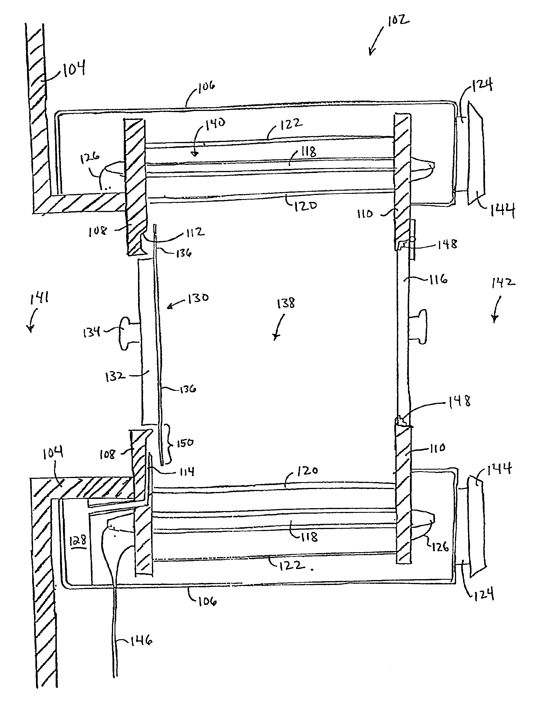
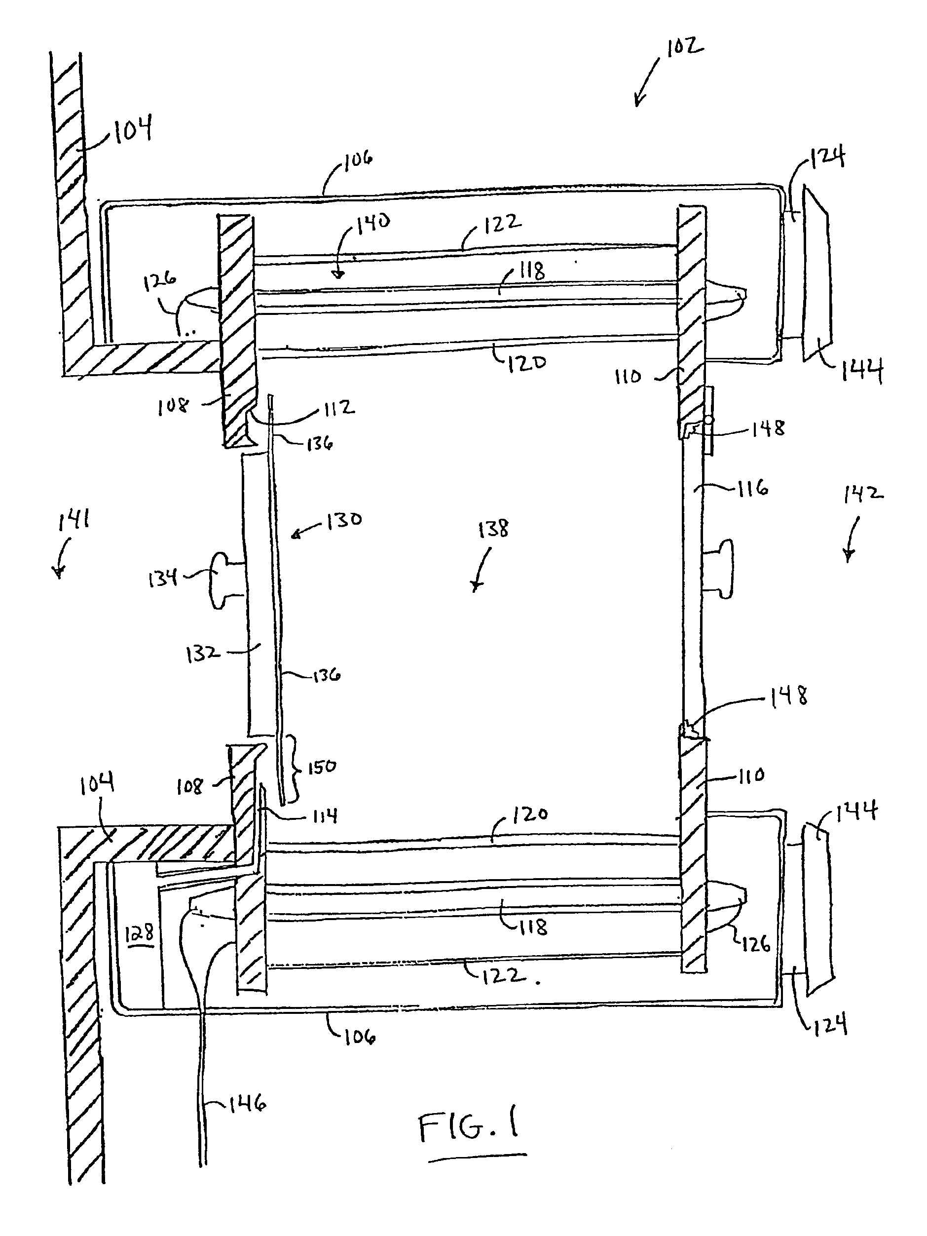
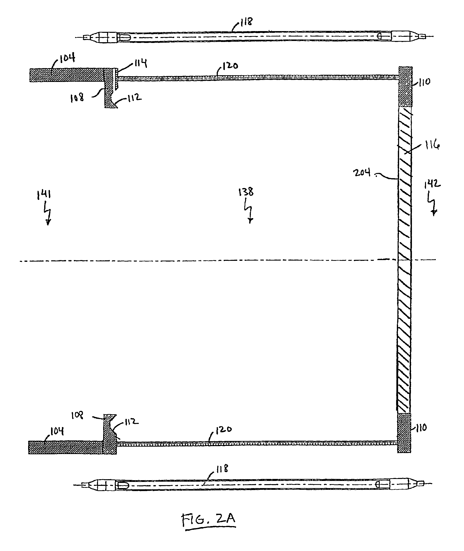
Referring first to FIG. 1, a cross sectional side view of a passthrough light treatment device integrated with a barrier isolator is shown, wherein the passthrough light treatment device employs a vacuum-sealable hatch to effectuate a sterilized vacuum seal in accordance with one embodiment of the invention. Shown is a passthrough device 102 and isolator walls 104 of an isolation chamber (not shown and also referred to as a barrier isolator). The passthrough device 102 includes an exterior shell 106, a first end wall 108 including a groove 112 and a vacuum port 114 (also referred to as a vacuum inlet 114) both on an interior surface of the first end wall 108, a second end wall 110, a sea...


PUM


Abstract

A vacuum-sealable hatch that is vacuum sealed to a surface of a passthrough light sterilization device, and related methods of use, consists of a hatch body having at least a portion adapted to fit within an opening of the treatment chamber and a flexible piece attached to the hatch body. The flexible piece extends peripherally from the hatch body and includes a seating portion which is adapted to be vacuum sealed to a seating region of an interior surface of the treatment chamber. The hatch body and the flexible piece seal the treatment chamber from the outside environment, thereby preventing the free flow of microorganisms to and from the treatment chamber and the outside environment. In some variations, at least the seating portion of the flexible piece is transmissive to the light treatment such that surfaces underneath the seating region are treated by the light treatment.

Description

BACKGROUND OF THE INVENTION1. Field of the InventionThe present invention relates to the light treatment chambers for treating objects placed therein, and more particularly to the sealing the light treatment chamber from the outside environment. Even more particularly, the present invention relates to a hatch for sealing an opening of the light treatment chamber from the outside environment.2. Discussion of the Related ArtA light treatment chamber is a device in which objects are treated with light to deactivate microorganisms on the objects. A passthrough treatment device is generally known in the art as a treatment device including a treatment chamber into which non-sterile objects are placed into from a “contaminated” or non-sterile environment, treated within the treatment chamber, and then retrieved out of the treatment chamber into a “clean” or sterile environment, such as within an isolation barrier or chamber. Passthrough treatment devices are commonly used in medical and ph...

Claims


Application Information

Patent Timeline
IPC IPC(8): A61L2/08A61L2/26A61L2/10
CPCA61L2/084A61L2/26A61L2/10A61L2202/122
Inventor BUSHNELL, ANDREW H.FRIES, WILLIAM M.
Owner PUREPULSE TECH
Why Eureka
Try Eureka