Orthogonal movement lateral shift zoom lens

a lateral shift and zoom lens technology, applied in the field of orthogonal movement can solve the problems of boresight pointing of the optical axis, limited zoom range, and limitations of lateral shift zoom lens relative to conventional axial shift zoom lens

Inactive Publication Date: 2005-02-01
RAYTHEON CANADA LTD
View PDF4 Cites 36 Cited by
  • Summary
  • Abstract
  • Description
  • Claims
  • Application Information

AI Technical Summary

Problems solved by technology

The lateral shift zoom lens has limitations relative to conventional axial shift zoom lens in image quality, b...

Method used


Image

  • Orthogonal movement lateral shift zoom lens
  • Orthogonal movement lateral shift zoom lens
  • Orthogonal movement lateral shift zoom lens

Examples


Embodiment Construction

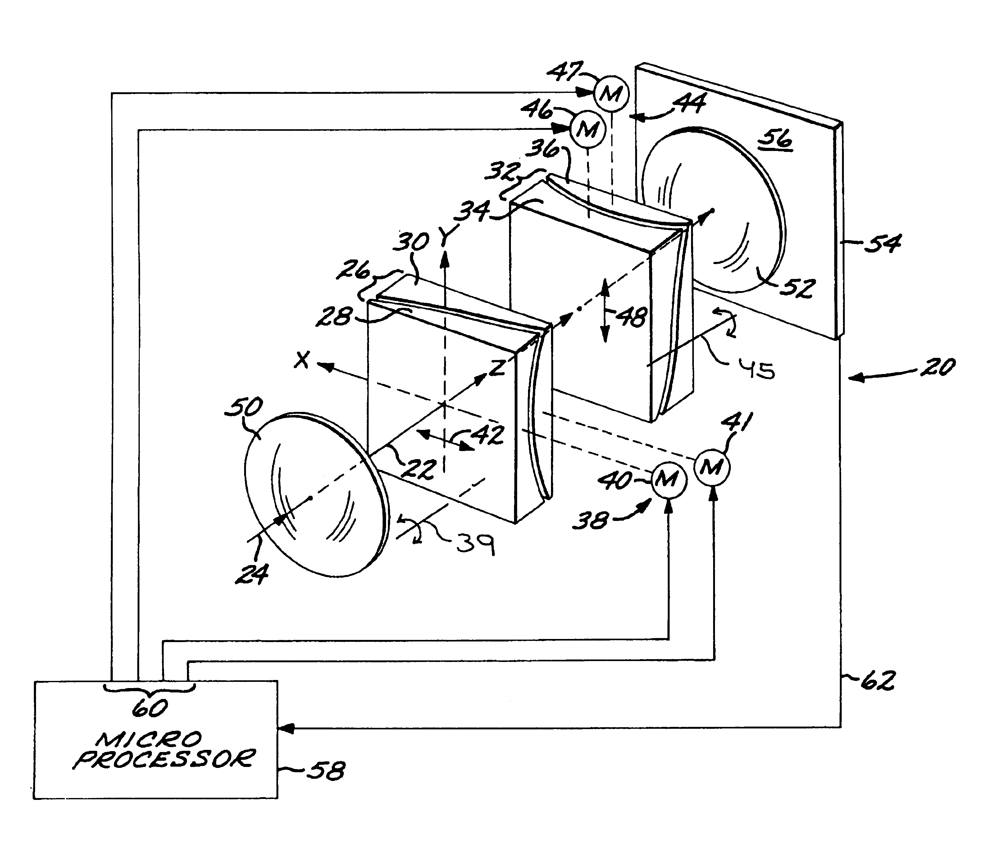
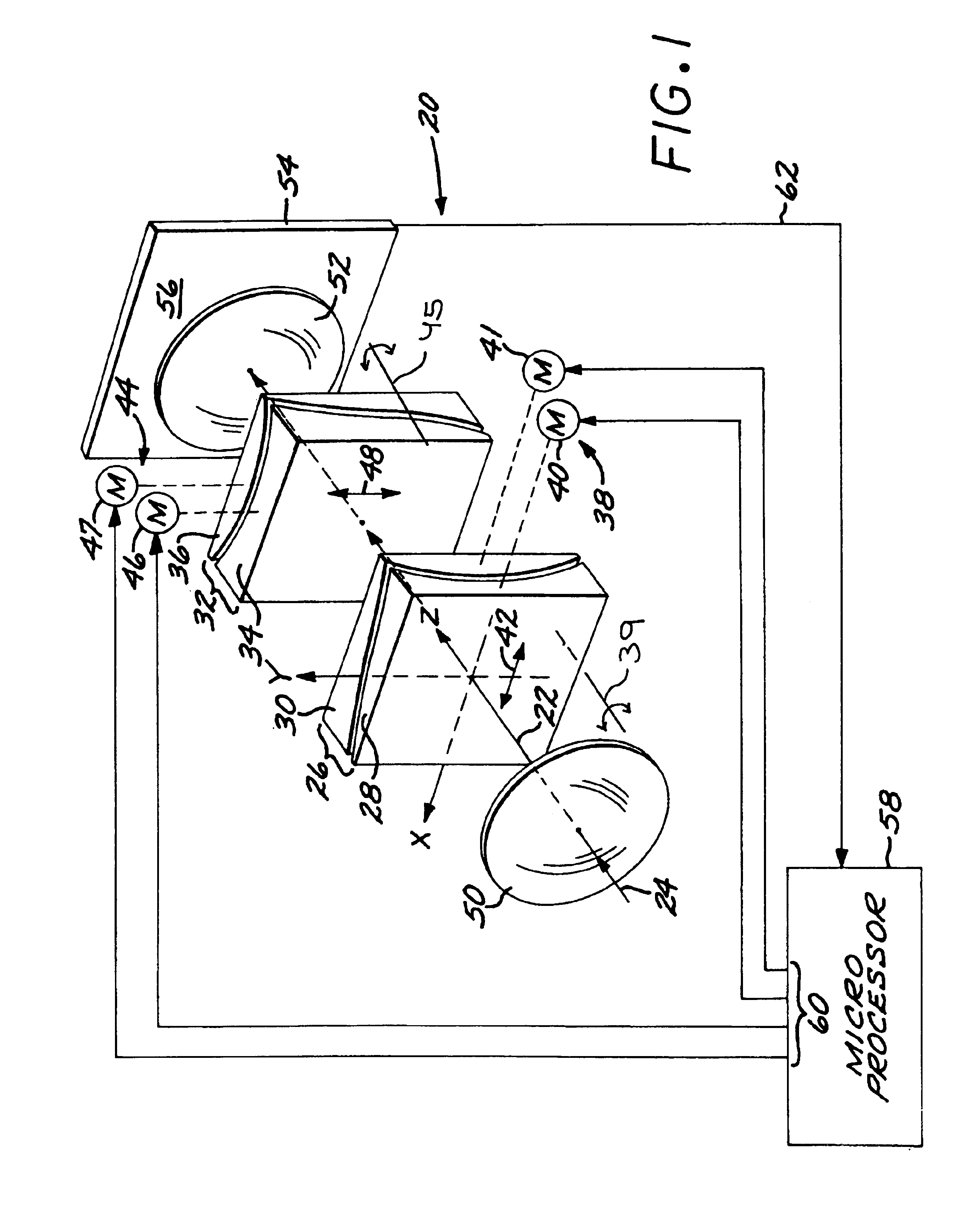
FIG. 1 depicts an optical zoom lens mechanism 20 arranged along an optical axis 22. As shown in FIG. 1, the optical axis 22 along which a light beam 24 is propagated lies coincident with a z-axis that is a boresight of the optical system. Absent the present approach, the optical axis 22 may shift away from the z-axis in an uncontrolled fashion as the optical zoom lens mechanism 20 operates. An x-axis and an orthogonal y-axis define a plane perpendicular to the z-axis, the optical axis 22, and the light beam 24. The optical zoom lens mechanism 20 comprises a first lens group 26 with at least two, and here illustrated as exactly two, adjacent transparent first optical lens plates 28 and 30. The first optical lens plates 28 and 30 are each rotationally nonsymmetric relative to the optical axis 22. That is, the lenses in conventional axial-translation zoom lenses are generally cylindrically symmetric when rotated about the optical axis. That is not the case for the first optical lens pl...


PUM


Abstract

An optical zoom lens mechanism is arranged along an optical axis and produces a zooming effect by a transverse movement of transparent elements perpendicular to the optical axis. A first lens group has two adjacent, rotationally nonsymmetric transparent first optical lens plates that are each rotationally nonsymmetric relative to the optical axis, and a first-group drive is operable to move the first optical lens plates together and relative to each other in a first-movement radial direction relative to the optical axis. A second lens group has two adjacent, rotationally nonsymmetric transparent second optical lens plates that are each rotationally nonsymmetric relative to the optical axis, and a second-group drive is operable to move the second optical lens plates together and relative to each other in a second-movement radial direction relative to the optical axis. The second-movement radial direction is angularly rotated from the first-movement radial direction by a nonzero, preferably about 90 degrees, rotational angle about the optical axis. The first optical lens plates and the second optical lens plates are shaped so that the relative movement of the first optical lens plates and second optical lens plates produces an optical zoom relative to a focal surface. The drives may be driven by a controller, such as a feedback controller having an imaging sensor located at the focal surface, and a microprocessor controller receiving an output of the imaging sensor and having a control output signal set operably connected to the drives.

Description

This invention relates to a lateral shift zoom lens and, more particularly, to controlling the shifting of the optical axis during optical zooming of the lens.BACKGROUND OF THE INVENTIONConventional optical zoom lenses function by moving sets of powered lens elements relative to each other along an optical axis. That is, the rotationally symmetric lens elements controllably move closer together and farther apart. This relative movement alters the focal length of the set of lens elements, producing a change in magnification of the set of lens elements and thence the zoom effect.Another type of zoom lens, termed herein a “lateral shift zoom lens”, achieves the zooming effect by movement of multiple pairs of optical lens plates perpendicular to the optical axis. The lateral shift zoom lens, described in U.S. Pat. No. 4,925,281, utilizes rotationally nonsymmetric optical lens plates. The optical lens plates have shapes selected such that, when the pairs of optical lens plates are moved ...

Claims


Application Information

Patent Timeline
IPC IPC(8): G02B15/00
CPCG02B15/00
Inventor STENTON, CONRAD
Owner RAYTHEON CANADA LTD
Why Eureka
Try Eureka