
Communication system to which multiple access control method is applied

Inactive Publication Date: 2005-02-01
REDWOOD TECHNOLOGIES LLC
View PDF8 Cites 33 Cited by
  • Summary
  • Abstract
  • Description
  • Claims
  • Application Information

AI Technical Summary

Benefits of technology

[0012]Therefore, an object of the present invention is to implement a communication system in which bandwidths are effectively utilized by reducing time for bandwidth reservation.
[0013]Another object of the present invention is to implement a communication system in which time between generating and transmitting data is shortened.

Problems solved by technology

The time requisite for transmission and reception thereof results in heavy overhead and bandwidth usage to a considerable degree.

Method used


Image

  • Communication system to which multiple access control method is applied
  • Communication system to which multiple access control method is applied
  • Communication system to which multiple access control method is applied

Examples


Embodiment Construction

owchart illustrating the procedure for a reservation phase on the transmitting station 1T side;

[0053]FIG. 10 is a detailed flowchart illustrating a data communication phase on the transmitting station 1T side;

[0054]FIGS. 11a to 11c are diagrams each showing information to be registered in a storage device 13R of the receiving station 1R;

[0055]FIGS. 12a and 12b are diagrams for each illustrating how to disassemble a communication reservation packet 103 and a data packet 104;

[0056]FIG. 13 is the first half of a sequence chart exemplarily illustrating how data is transmitted from the transmitting station 1T to the receiving station 1R;

[0057]FIG. 14 is the second half of a sequence chart exemplarily illustrating how data is transmitted from the transmitting station 1T to the receiving station 1R;

[0058]FIG. 15 is a sequence chart illustrating how data is exchanged between the transmitting station 1T and the receiving station 1R; and

[0059]FIG. 16 is a diagram for illustrating a communicat...


PUM


Abstract

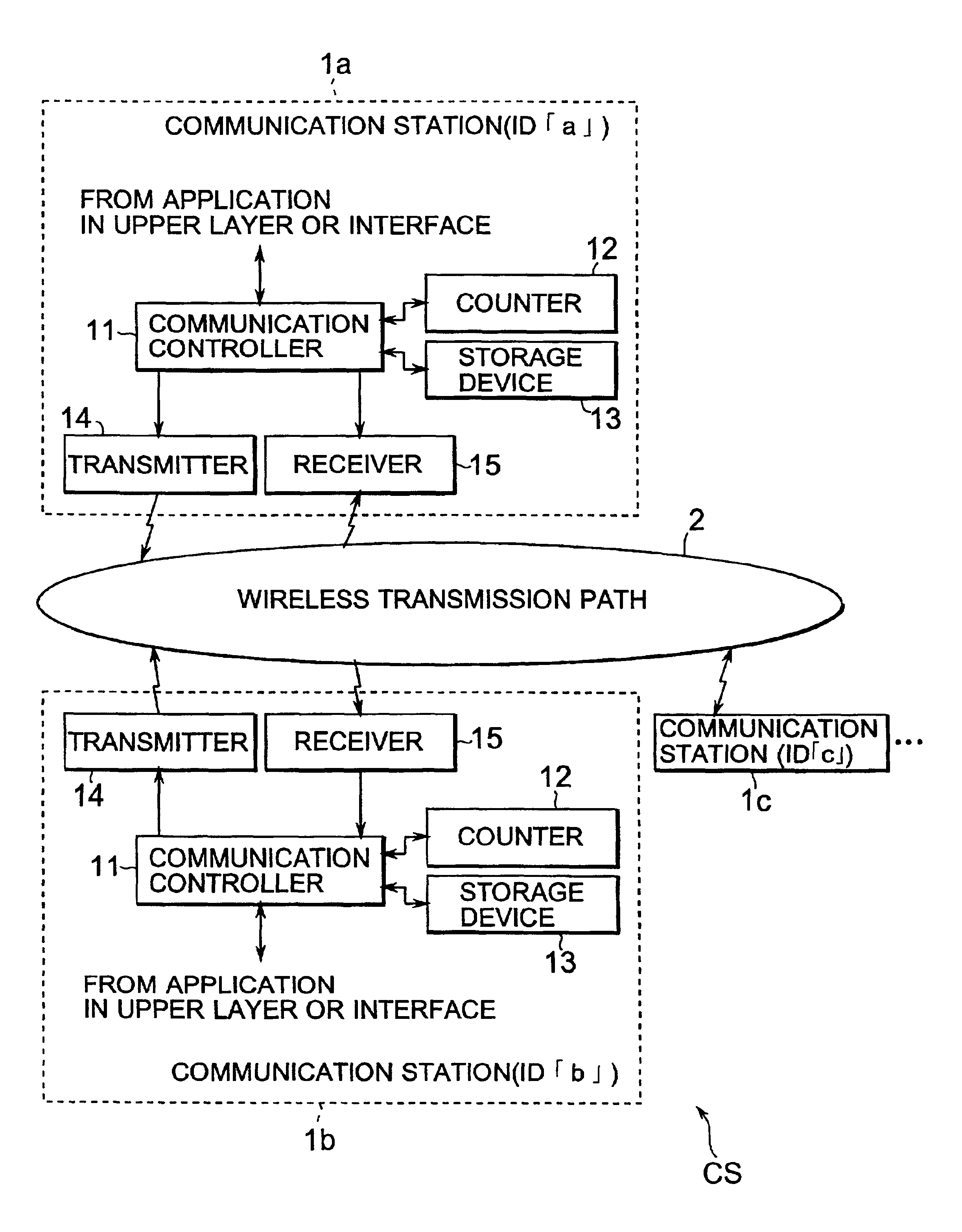
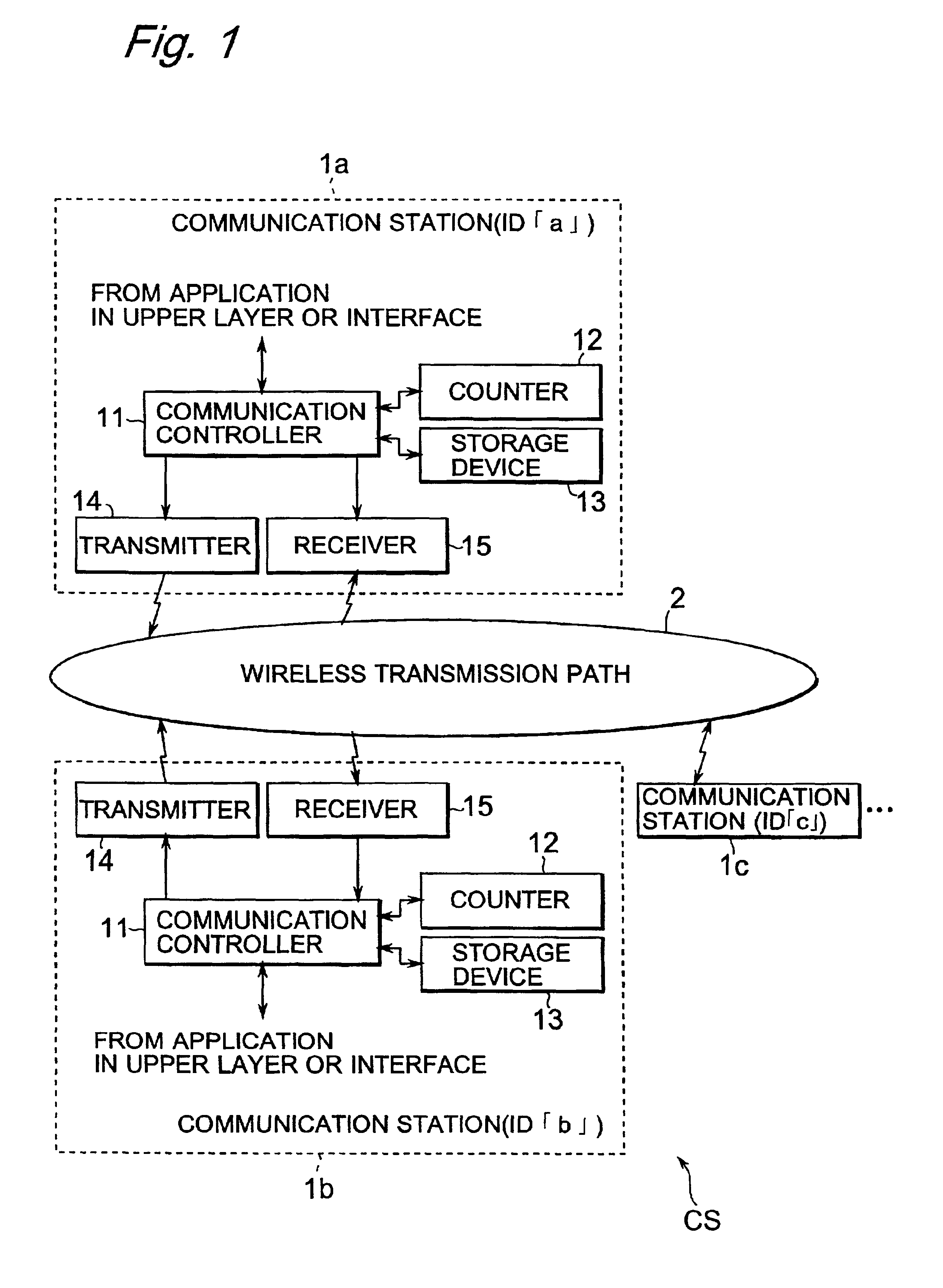
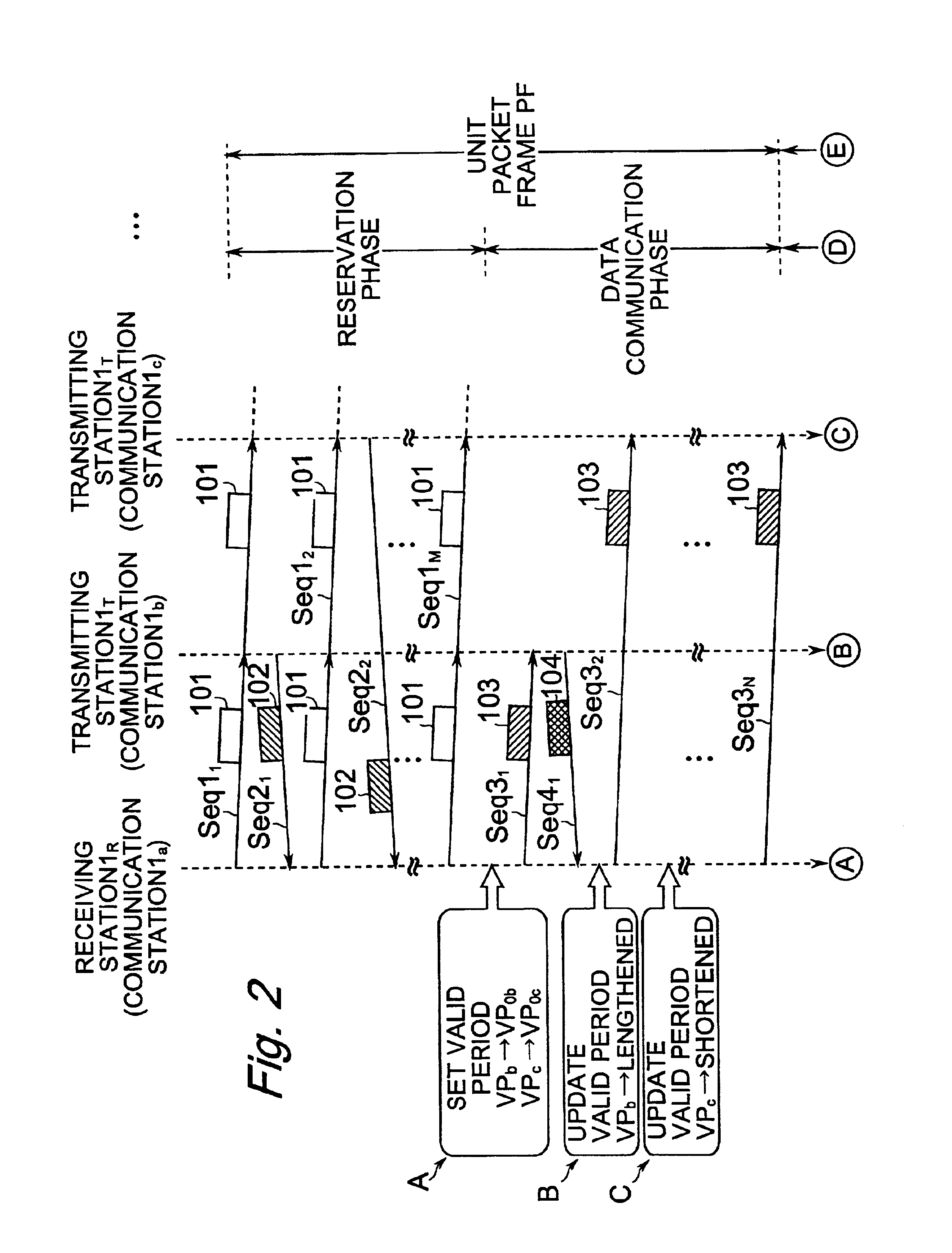
A communication system CS includes a plurality of communication stations and data communication is performed between any two communication stations, one is a transmitting station and the other is a receiving station. When any data for transmission is generated, the transmitting station transmits, to the receiving station, a reservation request packet for requesting bandwidth reservation. The receiving station reserves a bandwidth responding to the reservation request packet and then transmits a communication reservation packet to inform the transmitting station of the reserved bandwidth. The transmitting station creates a data packet and then transmits the created data packet through the informed bandwidth. The receiving station stores a valid period of the bandwidth reserved for the transmitting station, and voluntarily and repeatedly creates, for transmission, the communication reservation packet for the duration of the stored valid period. Accordingly, a communication system in which time for bandwidth reservation is shortened and thus bandwidths are effectively utilized is implemented.

Description

BACKGROUND OF THE INVENTION[0002]1. Field of the Invention[0003]The present invention relates to communication systems, and more particularly to a communication system in which a transmitting station and a receiving station are communicably connected through a transmission path, and the receiving station reserves a bandwidth, which is used in data communication, for the transmitting station in advance.[0004]2. Description of the Background Art[0005]Conventionally, a multiple access method has been applied to some communication systems. As an example thereof, “Splid-channel Reservation Multiple Access” (IEEE Trans. Commun., vol. COM-24, pp. 832 to 845, August 1976) is described next below by referring to FIG. 16. The communication system shown in FIG. 16 includes a central station 121, which controls bandwidths for communication, and secondary stations 122 and 123. Hereinafter, a description is made for a case where the secondary stations 122 and 123 transmit data to the central stat...

Claims


Application Information

Patent Timeline
IPC IPC(8): H04L12/56H04L1/00
CPCH04L1/0061H04L1/0072H04L1/08H04L12/5695H04L47/14H04L47/15H04W28/26H04L47/263H04L47/28H04L47/722H04L47/824H04L47/826H04L47/18H04L47/70H04W28/10H04W8/04
Inventor OMI, SHINICHIROANDO, KAZUHIROIMAI, HIROYUKI
Owner REDWOOD TECHNOLOGIES LLC
Learn More