Method and arrangements for fast transition from a low power state to a full power state in a communication system

a communication system and low power state technology, applied in power management, instruments, orthogonal multiplexes, etc., can solve the problems of incomplete transmission of low power data packets and inability to be used at the receiver, and achieve the effect of reducing the transition tim

Inactive Publication Date: 2005-02-01
RPX CORP
View PDF11 Cites 29 Cited by
  • Summary
  • Abstract
  • Description
  • Claims
  • Application Information

AI Technical Summary

Benefits of technology

An object of the present invention is to provide a method and arrangement for transition from the low power state to the full power state similar to the known one, but wherein the wake-up time to go from the low power state to the full power state is minimized.
Thus, similar to what happens in the known transition method, the transition from the low power state to the full power state may be announced by sending a predetermined state transition indication from the transmitter to the receiver. The receiver can detect this state transition indication for example by correlation techniques. Alternatively, provided that the receiver is able to discriminate a data packet transmitted at full power from a data packet transmitted at low power, the transition from the low power state to the full power state can be initiated by transmitting a data packet at full power without first transmitting a predetermined state transition indication. The latter alternative requires a more complex receiver equipped with a power measurement device, but enables to even more reduce the transition time from the low power state to the full power state.

Problems solved by technology

The incompletely transferred low power data packet for evident reasons can not be used at the receiver's side and consequently it is required to re-send at full power the whole data packet whose transfer has been interrupted.

Method used


Image

  • Method and arrangements for fast transition from a low power state to a full power state in a communication system
  • Method and arrangements for fast transition from a low power state to a full power state in a communication system
  • Method and arrangements for fast transition from a low power state to a full power state in a communication system

Examples


Embodiment Construction

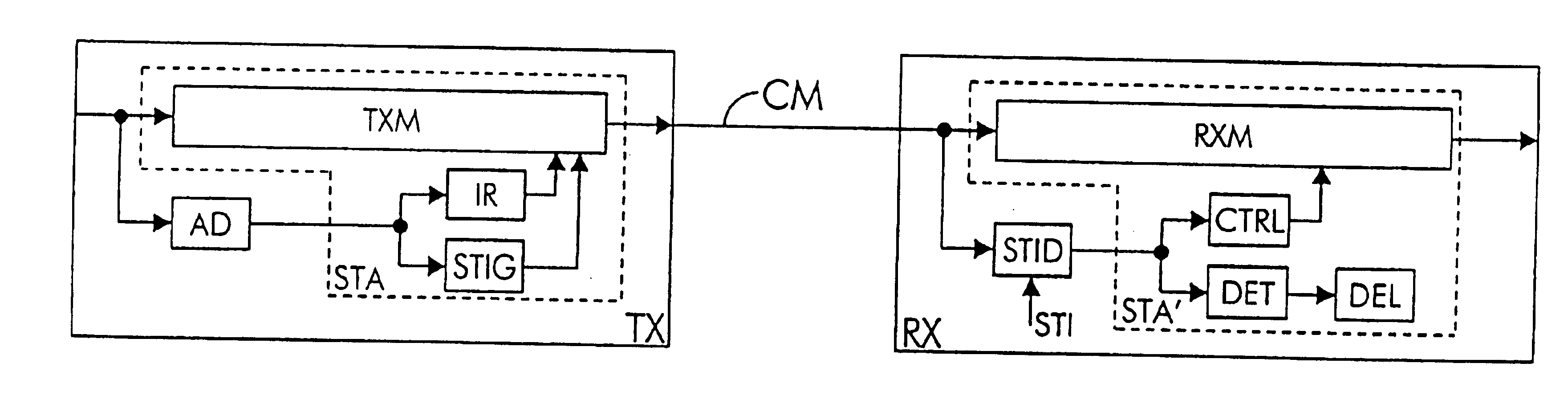
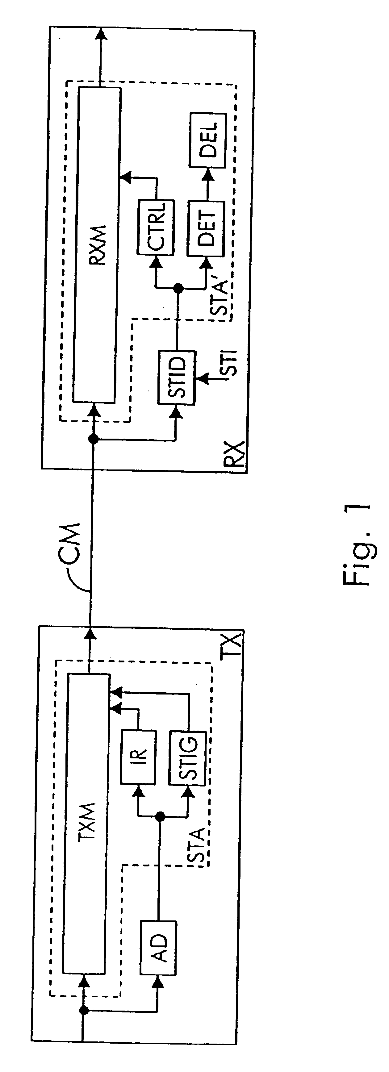
The communication system drawn in FIG. 1 contains an ADSL (Asymmetric Digital Subscriber Line) transmitter TX, a twisted pair telephone line CM, and on ADSL receiver RX. The ADSL transmitter includes a activity detector AD and a state transition arrangement STA comprising a DMT (Discrete Multi Tone) transmitter TXM, an interrupting device IR and a state transition indication generator STIG. The ADSL receiver RX includes a state transition indication detector STID and a state transition arrangement STA′ comprising a DMT (Discrete Multi Tone) receiver RXM, a control unit CTRL, an interrupted symbol detector DET, and an interrupted symbol deletion device DEL.

In the ADSL transmitter TX, the DMT transmitter TXM is coupled between an input terminal of the ADSL transmitter TX adapted to receive ATM (Asynchronous Transfer Mode) cells and an output terminal of the ADSL transmitter TX adapted to source DMT (Discrete Multi Tone) symbols. The activity detector AD is coupled to the input termina...


PUM


Abstract

In a full power state, data packet are transferred at full power from a transmitter to a receiver, whereas in a low power state data packet s are transferred at low power from the transmitter to the receive. To transit fast from the low power state to the full power state, the transmitter interrupts transmission of the currently transmitted low power data symbol and transmits a copy of the currently transmitted low power symbol at full power to the receiver.

Description

BACKGROUND OF THE INVENTIONThe present invention relates to a method to transit in a communication system from a low power state to a full power state, an arrangement to be used to transit from the low power state to the full power state in a transmitter and an arrangement to transit from the low power state to the full power state in a receiver.Such a state transition method and arrangement to perform such a state transition are already known in the art, e.g. from the temporary document WH-031 submitted on Jun. 29, 1998 to ITU Study Group 15 which is an ADSL (Asymmetric Digital Subscriber Line) forum. This document with reference WH-031 is entitled ‘Time Domain Rate Adaptation Based L1 State for C. Lite Modem Power Down Management’ and originates from IteX. In this document, a mechanism for transition between a so called L1 state, a low power / low bit rate state, to a so called L0 state, a full power / full bit rate state, of an ADSL (Asymmetric Digital Subscriber Line) system is desc...

Claims


Application Information

Patent Timeline
Patent Type & Authority Patents(United States)
IPC IPC(8): H04L1/00H04B7/005H04L27/26H04J11/00H04L29/06
CPCH04W52/38H04W52/04H04L1/0002Y02B60/50
Inventor CASSIERS, RAPHAEL PAUL CLAUDE ANDREREUSENS, PETER PAUL FRANSVAN BRUYSSEL, DANNY
Owner RPX CORP
Why Eureka
Try Eureka