
Method and apparatus for reception quality indication in wireless communication

a wireless communication and signal quality technology, applied in the field of wireless communication systems, can solve the problems of network communication quality drop, rssi drop, etc., and achieve the effect of avoiding burden on users and more accurate determination and indication of received signal quality

Inactive Publication Date: 2005-02-01
PANASONIC CORP
View PDF16 Cites 101 Cited by
  • Summary
  • Abstract
  • Description
  • Claims
  • Application Information

AI Technical Summary

Benefits of technology

The advantages of the present invention include: (i) more accurate determination and indication of received signal quality, by measuring the signal parameter(s) that matter in actually performing communication, such as BER for a digital system, or SNR for an analog system, (ii) adaptable for use with a broad range of wireless communication systems with little or no modification to the infrastructure of the system and (iii) compatibility with existing display methods to avoid burdening users with the need to familiarize themselves with a new metric.

Problems solved by technology

However, customers do notice that the RSSI has dropped, and mistakenly interpret this as a drop in network communications quality.

Method used


Image

  • Method and apparatus for reception quality indication in wireless communication
  • Method and apparatus for reception quality indication in wireless communication
  • Method and apparatus for reception quality indication in wireless communication

Examples


Embodiment Construction

The present invention is directed to an apparatus and method capable of determining and indicating received signal quality for use in a wireless communication system.

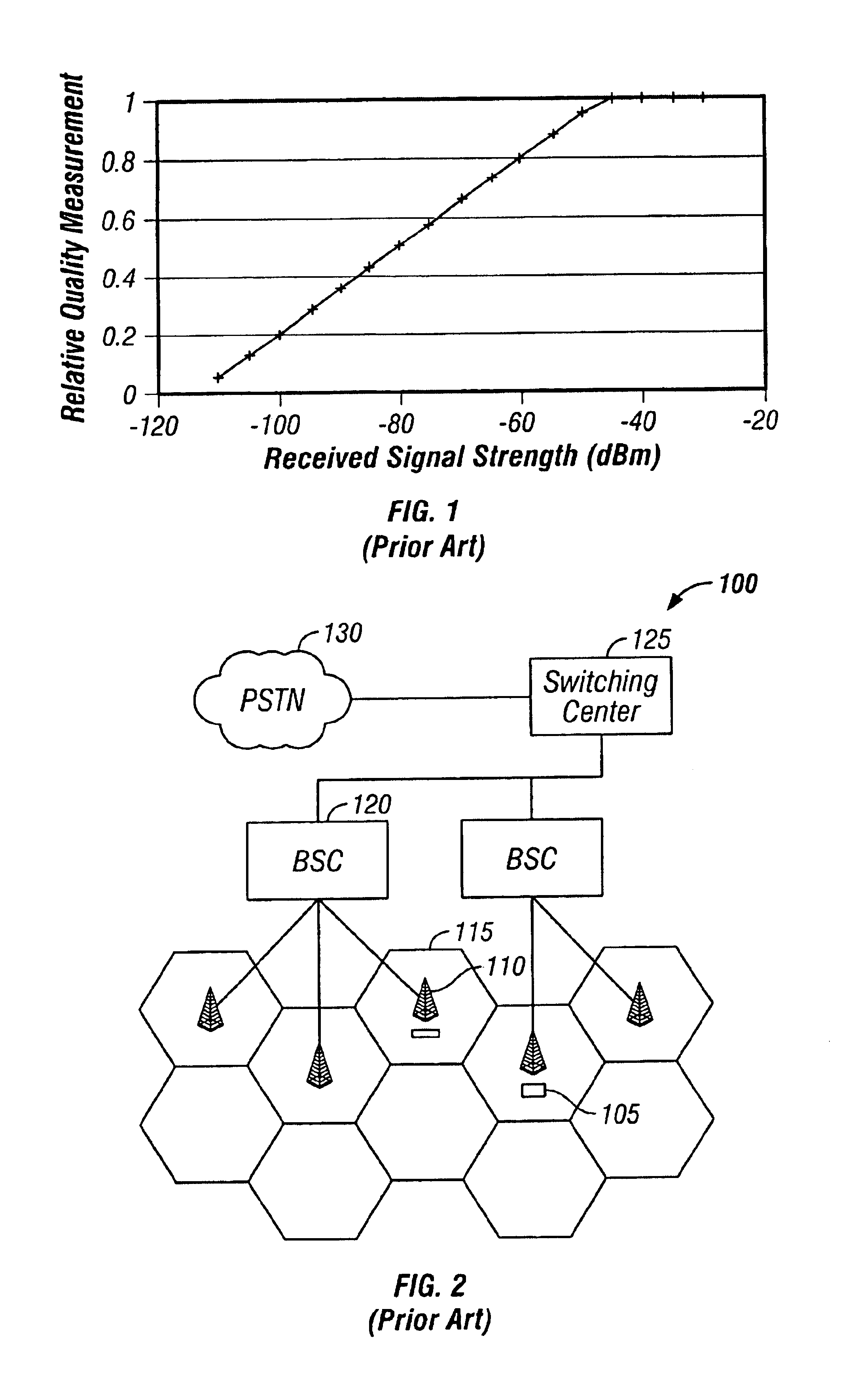
FIG. 2 shows an exemplary block diagram of a wireless communication system 100, here a mobile telecommunication system or system, for which a received signal quality indicator and method according to an embodiment of the present invention are particularly useful. For purposes of clarity, many of the details of mobile telecommunication systems that are widely known and are not relevant to the present invention have been omitted. Mobile telecommunication systems, and bit-error rate estimation in particular, are described in more detail in, for example, U.S. Pat. No. 6,163,571, which is incorporated herein by reference.

Referring to FIG. 2, the wireless communication system 100 generally includes a number of first wireless communication devices or mobile handsets 105, and one or more second wireless communication devices or...


PUM


Abstract

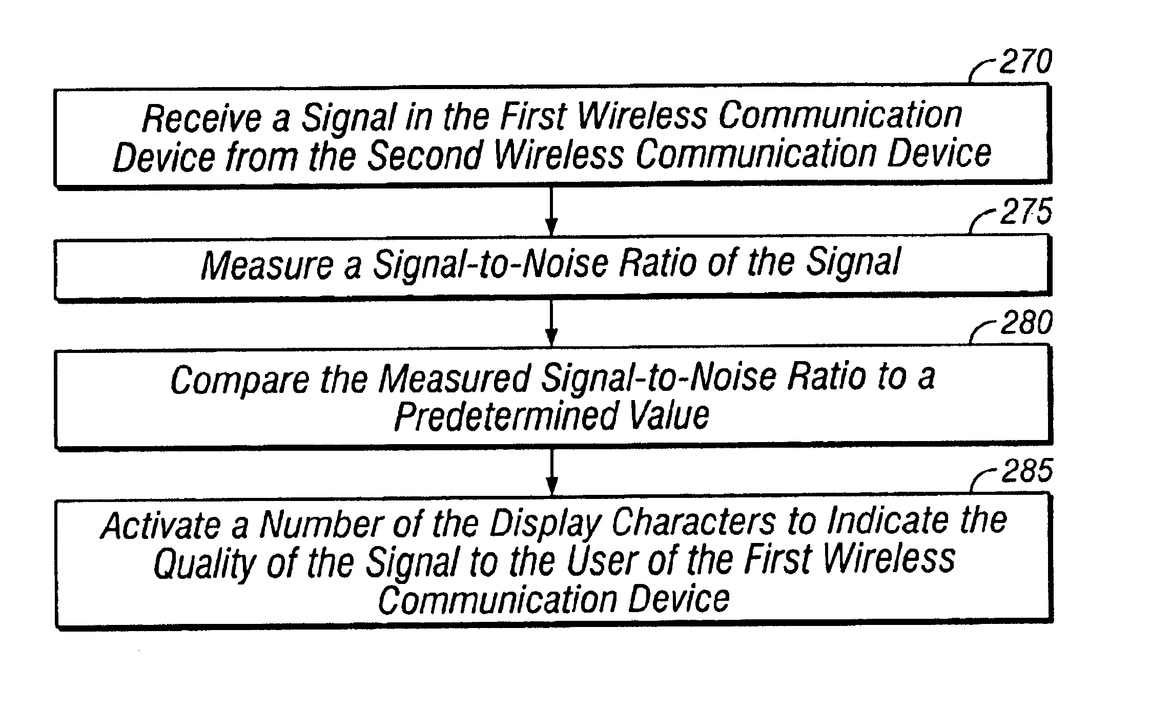
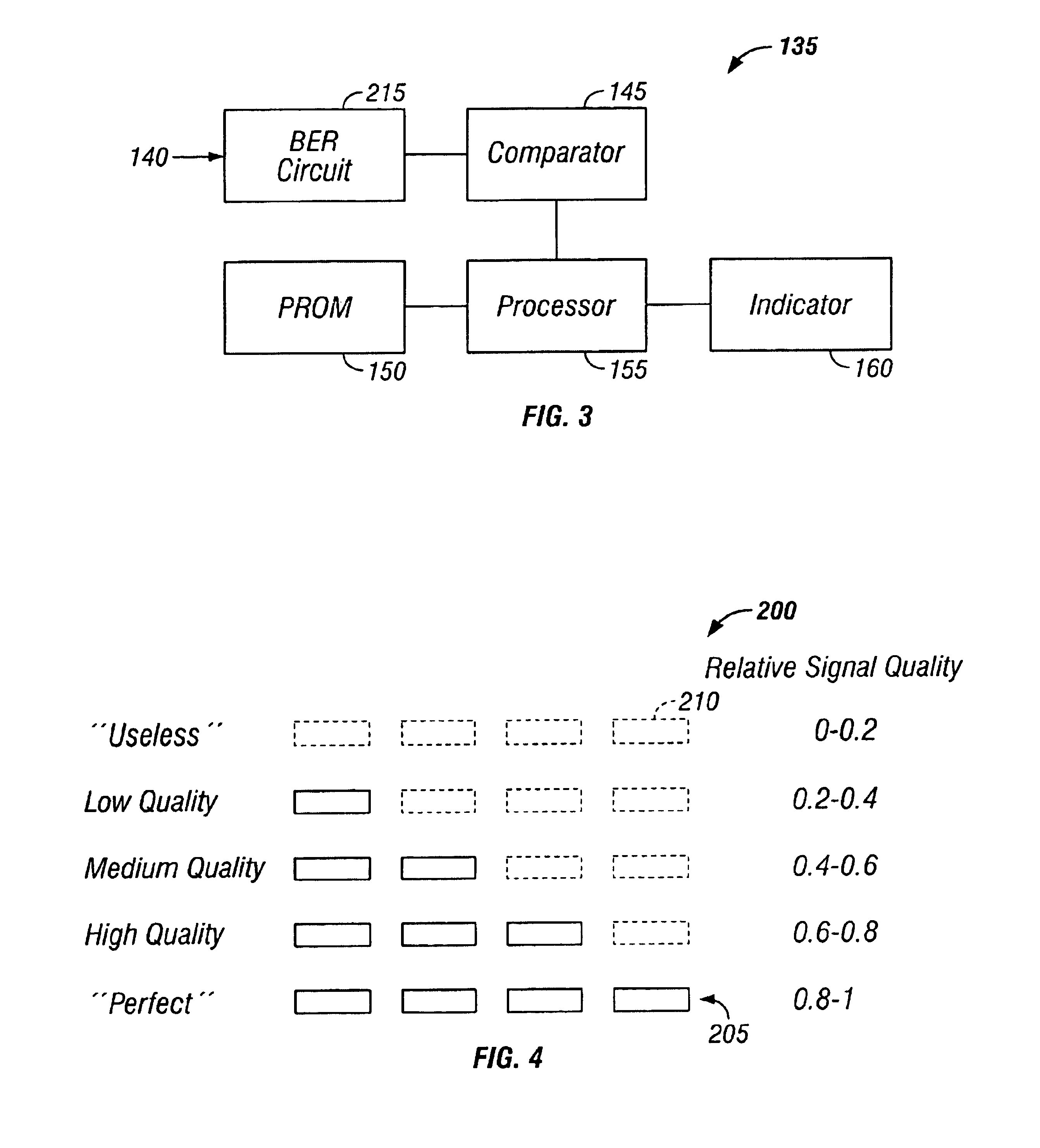
An apparatus (135), method and computer program are provided for determining and indicating a quality of a signal received by a first wireless communication device (105) from a second wireless communication device (110). In one embodiment, the apparatus (135) includes a bit-error-rate (BER) circuit (215) for measuring a BER of the signal, a comparator (145) for comparing the BER with a predetermined value to determine a relative signal quality, and an indicator (160) for indicating the quality of the signal to a user of the first device (105). Alternatively, the apparatus (135) includes a circuit for measuring the strength of the signal (230), a calculator (235) for calculating a signal-to-noise ratio (SNR) of the signal using the strength of the signal and a predetermined noise value, and a comparator (145) for comparing the SNR with a predetermined value to determine a relative signal quality. Signal quality is indicated by activating a number of characters (210) corresponding to the relative signal quality.

Description

FIELDThe present invention relates generally to wireless communication systems, and more particularly to a method and apparatus for indicating signal quality of a signal received by a first wireless communication device from a second wireless communication device.BACKGROUNDRecent years have seen explosive growth in the use of wireless communication systems. For example, wireless systems are commonly used in mobile telecommunication systems, such as cellular and personal communication systems (PCS), to provide voice communication, in wireless modems and network connections enable the transfer of data without a physical link between computers, and in satellite systems to transmit and receive audio and television programming.A common feature of wireless communication systems is that a wireless device, a receiver or transceiver, often includes an apparatus or circuit for determining a quality of the received signal. Occasionally this determination of received signal quality is displayed...

Claims


Application Information

Patent Timeline
Patent Type & Authority Patents(United States)
IPC IPC(8): H04B17/00H04Q7/34H04W24/00
CPCH04W24/00H04B17/318H04B17/23
Inventor MCCUNE, JR., EARL W.
Owner PANASONIC CORP
Learn More