
Utilizing increasing width for identification voltages

a technology of identification voltage and width, applied in the direction of electrical control, pulse technique, instruments, etc., can solve the problems of increasing the possibility of error and and achieve the effect of maintaining the likelihood of reading error small

Inactive Publication Date: 2005-02-08
VITESCO TECH USA LLC
View PDF15 Cites 0 Cited by
  • Summary
  • Abstract
  • Description
  • Claims
  • Application Information

AI Technical Summary

Benefits of technology

The invention is about identifying different systems using unique identification voltages. These voltages are associated with specific combinations of characteristics for each system. The distance between adjacent voltages and the minimum to maximum range of each code increase as the voltage increases, reducing the likelihood of reading errors. The codes can be associated with fuel injectors or other systems. The invention also includes determining the center of each identification code and scaling up the values to determine boundaries between them. This helps to accurately identify and distinguish different systems.

Problems solved by technology

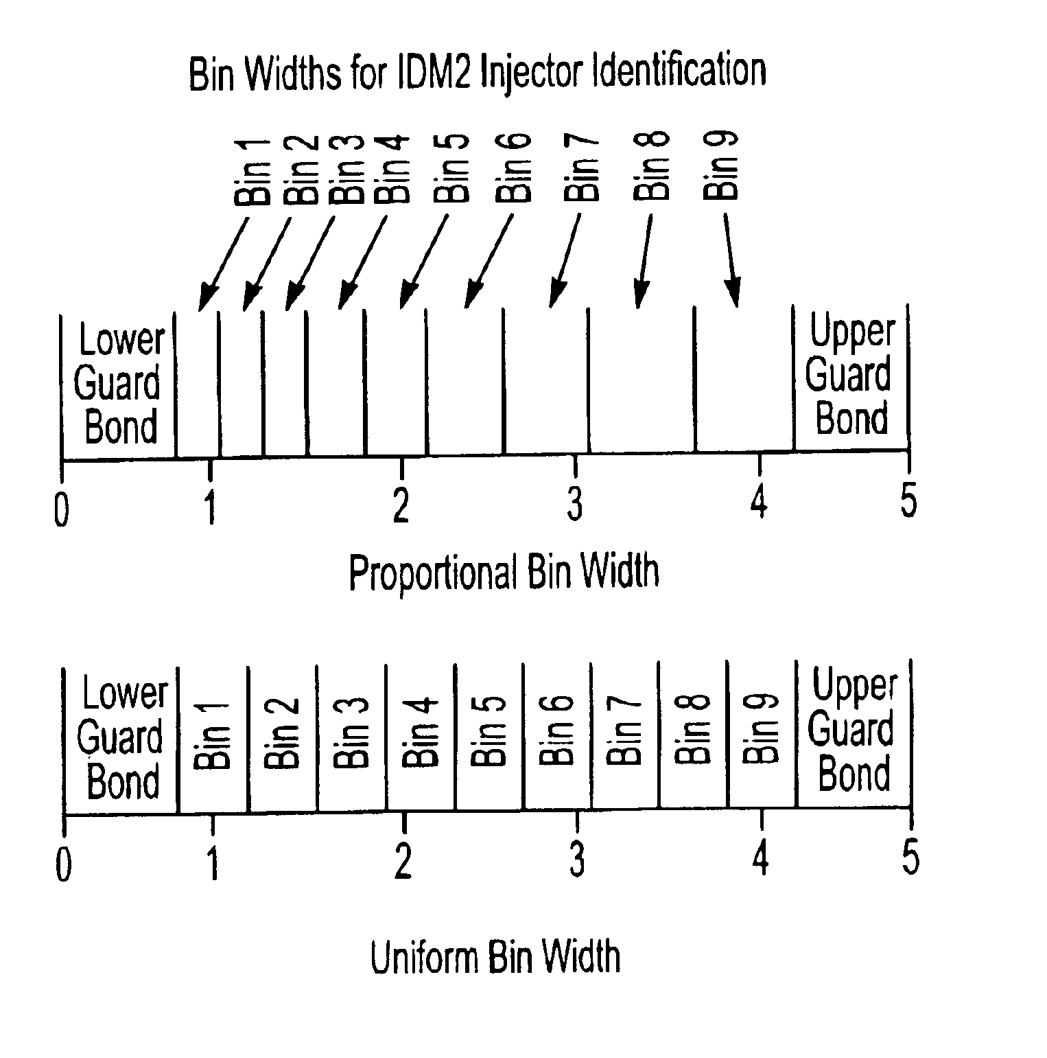
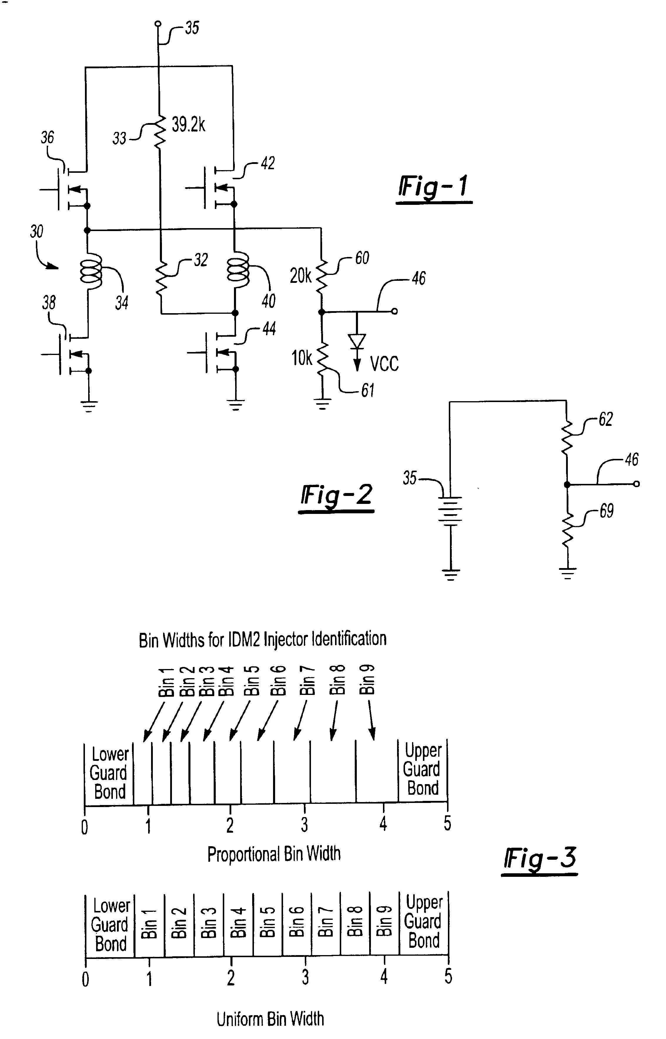
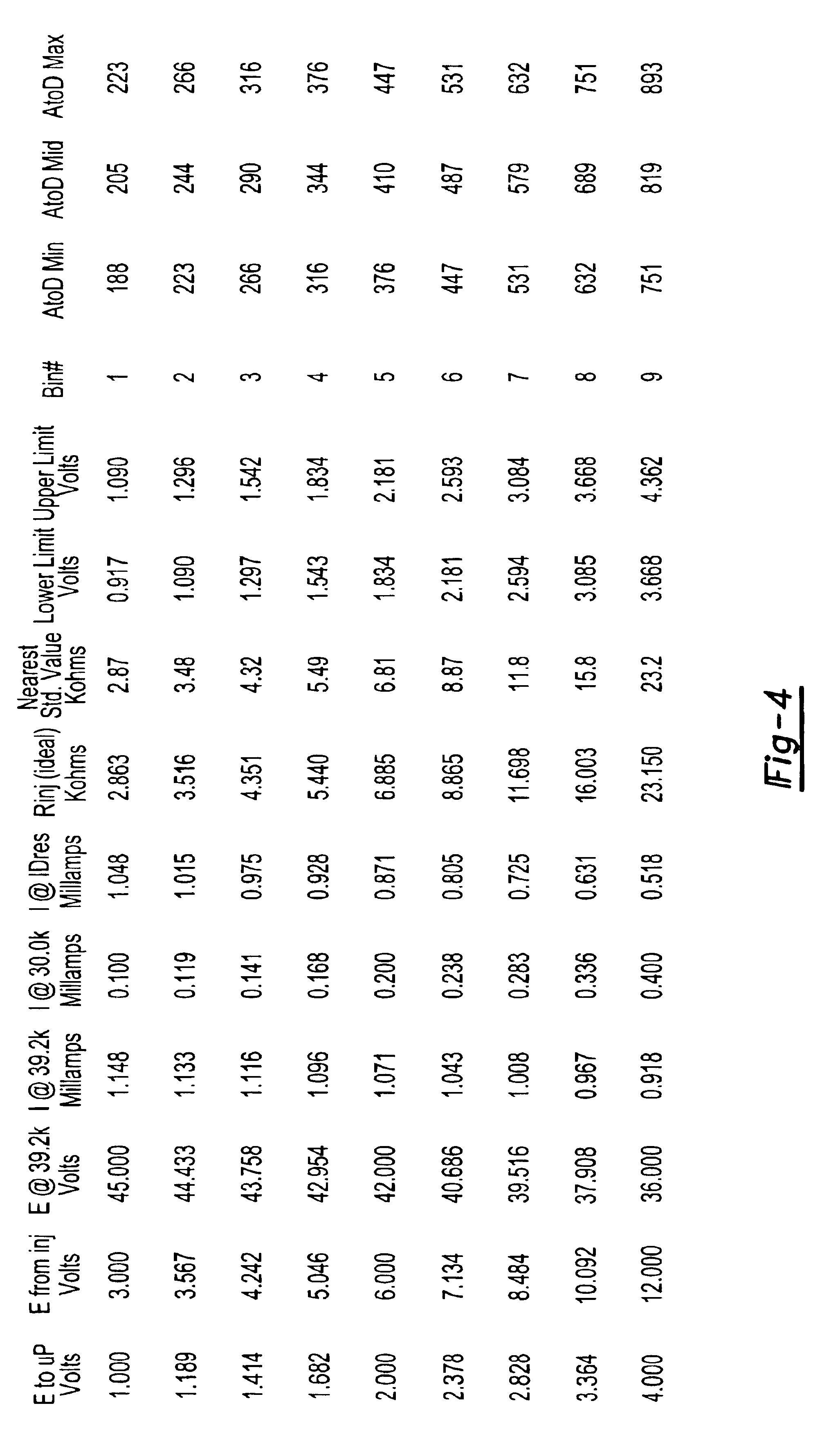
In this way, with increasing voltage the possible error will increase, but since the band or distance between the adjacent codes also increases, the likelihood of a reading error is maintained small.

Method used


Image

  • Utilizing increasing width for identification voltages
  • Utilizing increasing width for identification voltages
  • Utilizing increasing width for identification voltages

Examples


Embodiment Construction

FIG. 1 shows a fuel injector system 30 wherein a representative resistor 32 is varied to provide a plurality of output codes. This circuit, its benefits and further details are all best explained in co-pending U.S. patent application Ser. No. 09 / 536,365 filed on Mar. 27, 2000, and entitled “IDENTIFICATION OF DIESEL ENGINE INJECTOR CHARACTERISTICS”. This co-pending application was invented by one of the inventors of this application.

Open and close coils 34 and 40 are associated with upper and lower drivers 36 and 38, and 42 and 44, respectively. A connection 35 to a voltage source passes through a resistance 33. Resistors 60 and 61 lead to a connection 46 which is associated with a control. By controlling the drivers 36, 38, 42 and 44, and selectively energizing certain drivers, a control can sense an output voltage from this circuit. In a disclosed embodiment, all of the drivers are left open, with the driver 44 closed. The circuit then becomes effectively as shown in FIG. 2, with t...


PUM


Abstract

A method and system is disclosed by which identification codes for a plurality of systems are utilized to provide a control with an indication of a particular characteristic of the particular system. The characteristic is assigned with an identifying variable, in a disclosed embodiment voltage, which increases. As this variable increases, possible errors due to system features will also increase. Thus, the possibility of the control misreading an identification code due to the error increases. To address this increasing possibility, the distance between adjacent variables also increases as the variables themselves increase. In a preferred embodiment the distance is increased proportionally.

Description

BACKGROUND OF THE INVENTIONThis invention relates to a method of increasing the width of a band of voltages associated with a particular identification code as the voltages themselves increase.The present invention is specifically directed to a disclosed system wherein an identification voltage is associated with particular types of fuel injectors to provide a control feedback on characteristics of those fuel injectors. A series of distinct voltages are associated with different combinations of two characteristics. The control can read an electric signal which is influenced by the voltages, and can thus identify the particular combination of characteristics. One problem with this type of system is the reduction or elimination of identification errors. Thus, it would be desirable to minimize the occurrences of when a particular monitored voltage is associated with a particular set of characteristics by the control, but wherein the injector actually possesses a different set of charac...

Claims


Application Information

Patent Timeline
Patent Type & Authority Patents(United States)
IPC IPC(8): F02D41/00F02D41/24F02D45/00H03K17/695
CPCF02D41/2409F02D41/2419F02D41/2467F02D41/2435F02D41/2422
Inventor VIERLING, LOUHILTUNEN, LARRY
Owner VITESCO TECH USA LLC
Learn More