Method to produce a scintillator-photosensor sandwich, scintillator-photosensor sandwich, and radiation detector

a technology of scintillator and photosensor, which is applied in the direction of radiation intensity measurement, instruments, x/gamma/cosmic radiation measurement, etc., can solve the problem of expensive known work process

Active Publication Date: 2014-04-08
SIEMENS HEALTHCARE GMBH
View PDF2 Cites 1 Cited by
  • Summary
  • Abstract
  • Description
  • Claims
  • Application Information

AI Technical Summary

Benefits of technology

[0007]An object of the invention to find an alternative production method for an x-ray detector or an x-ray detector element in which the combination of scintillator layer and photosensor layer is produced more simply and securely.
[0009]A marked simplification compared to the prior art results in the described vacuum solutions, due to the frame. It is therefore also possible to simply produce both adhesive connections under vacuum (to avoid air inclusions). Given lamination the frame offers the possibility to adhere both function layers to be combined in one work step. It is an additional advantage that a closed small space can be achieved, and advantageously the adhesive side (without the removed protective film) is always directed downward. The possibility of interfering particle inclusions on the function layer is thus markedly reduced.
[0016]The production method is significantly simplified by this use of a support frame in the connection to the at least one side of the adhesive layer with a function layer. In particular, it is advantageous that the adhesive layer is directed downward upon application of the function layer, so there is a significantly smaller likelihood of contamination of the sensor surface.
[0019]However, it is more advantageous if the laminar assembly of the adhesive layer and the first function layer occurs under vacuum, at least in the region between the adhesive layer and the first function layer.

Problems solved by technology

It is problematic that this known work process is expensive, particularly due to the fact that the production process is implemented in part under vacuum.

Method used


Image

  • Method to produce a scintillator-photosensor sandwich, scintillator-photosensor sandwich, and radiation detector
  • Method to produce a scintillator-photosensor sandwich, scintillator-photosensor sandwich, and radiation detector
  • Method to produce a scintillator-photosensor sandwich, scintillator-photosensor sandwich, and radiation detector

Examples


Embodiment Construction

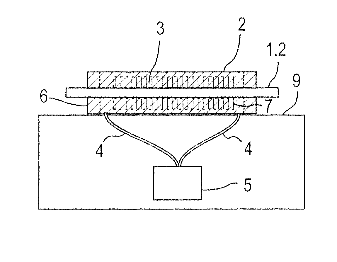
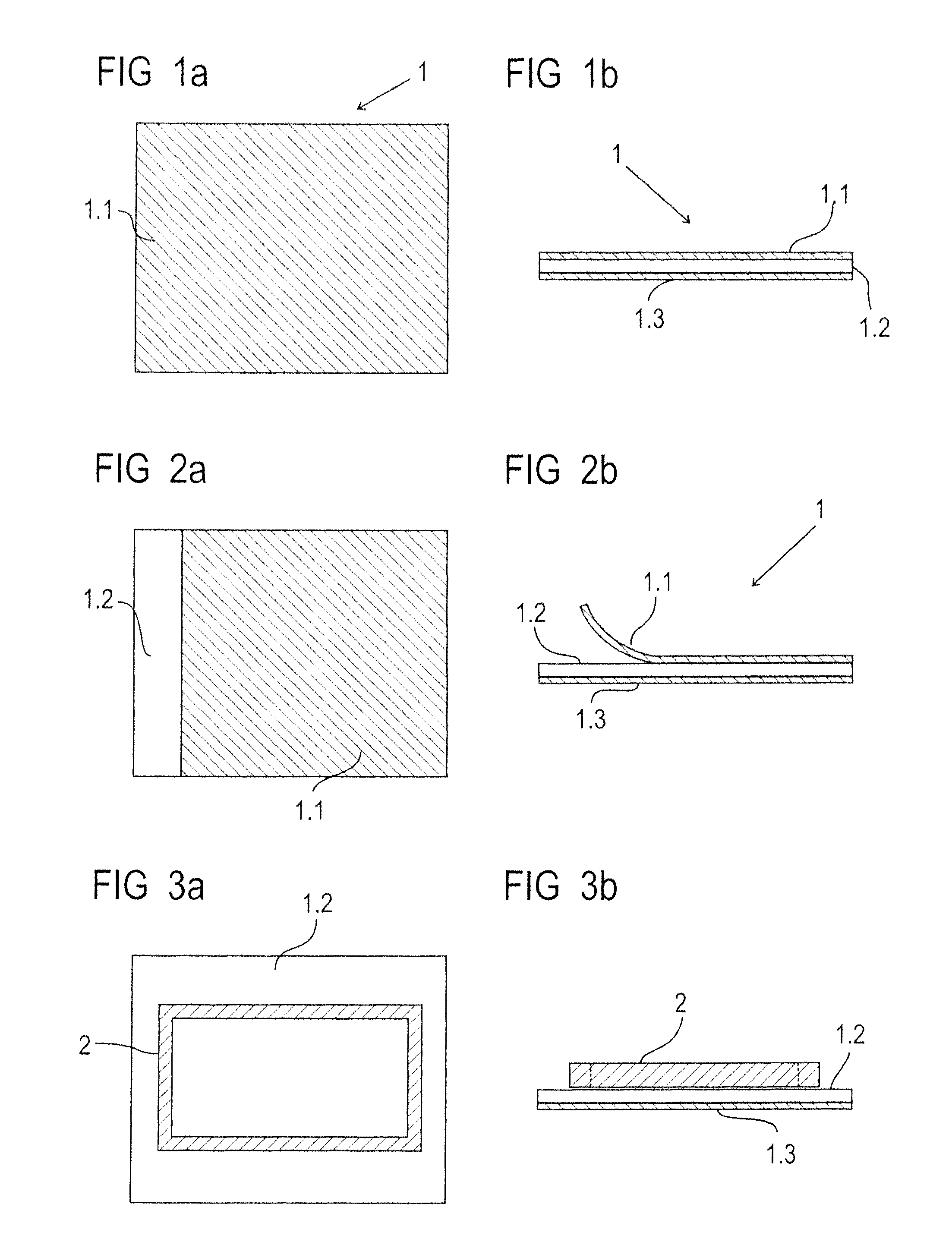
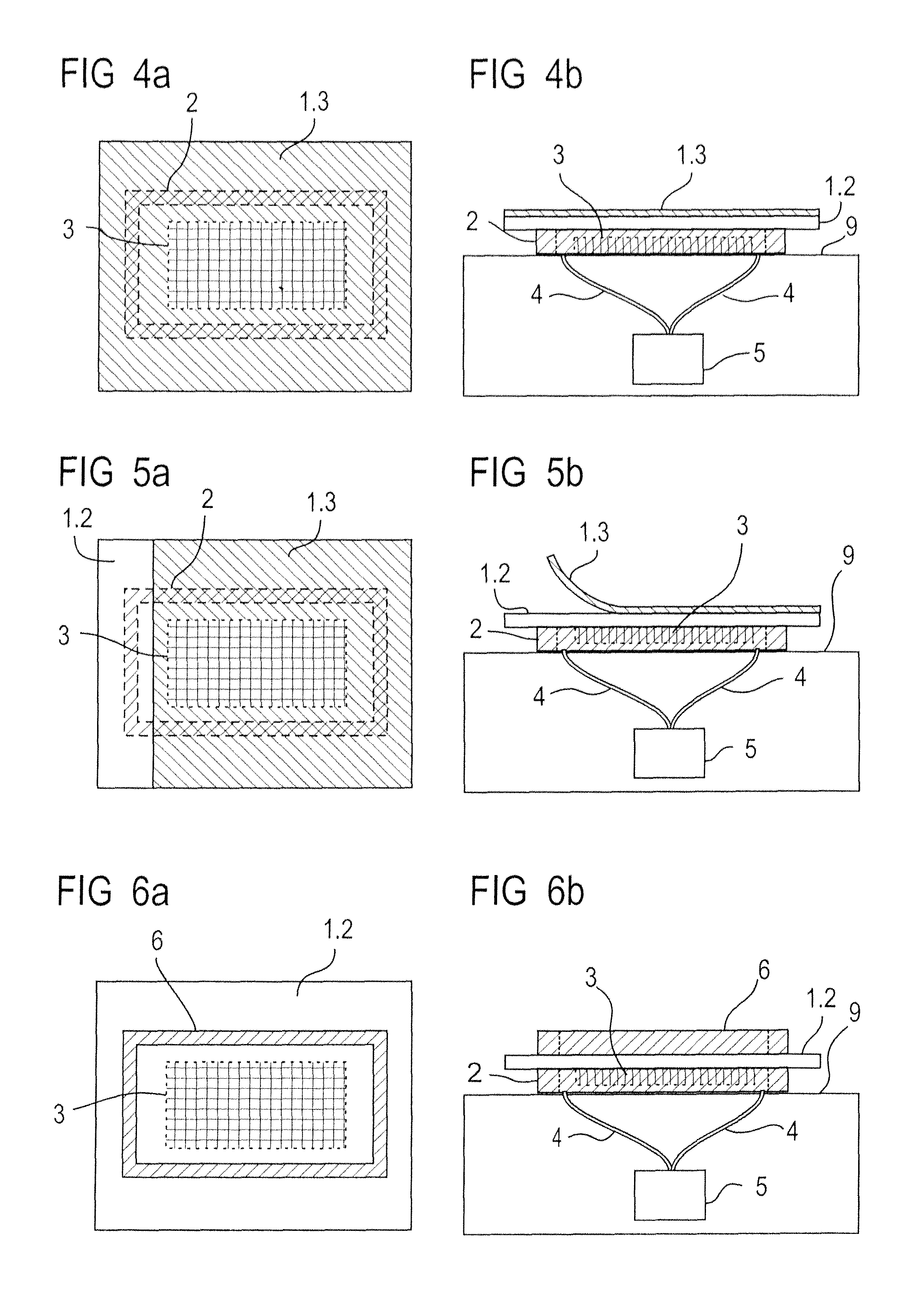
[0029]In the following the invention is described in detail in the figures, wherein only the features necessary to understand the invention are shown. The following reference characters are used: 1: transfer adhesive tape; 1.1: first protective film; 1.2: adhesive layer; 1.3: second protective film; 2: first support frame; 3: first function layer; 4: vacuum connections; 5: vacuum pump; 6: second support frame; 7: second function layer; 8: scintillator-photosensor sandwich; 9: support.

[0030]A preferred embodiment of the method according to the invention is shown in FIGS. 1a, 1b through 9a, 9b. FIGS. 1a through 9a respectively show an overview while FIGS. 1b through 9b respectively show a side view.

[0031]A transfer adhesive tape 1 is shown in FIGS. 1a and 1b, in which an adhesive layer 1.2 is covered on both sides by two protective films 1.1 and 1.3. Assuming such an adhesive tape 1, in FIGS. 2a and 2b it is shown how the first protective film 1.1 is lifted from the adhesive layer 1.2...


PUM

PropertyMeasurementUnit
sizeaaaaaaaaaa
volumeaaaaaaaaaa
vacuumaaaaaaaaaa

Abstract

A scintillator-photosensor sandwich is generated by gluing a first support frame onto an adhesive layer (covered with a protective film on the side facing the adhesive layer, the first frame having a size that (in terms of area) surrounds the scintillator-photosensor sandwich to be produced. The first support frame is placed onto a flat base that supports a first function layer (either a scintillator layer or a photosensor layer). The adhesive layer supported on the first support frame and the first function layer are laminarly assembled. The protective film is removed from the adhesive layer and a second function layer (the other of the scintillator layer or the photosensor layer not used as the first function layer) is assembled with the first function layer with the interposed adhesive layer.

Description

BACKGROUND OF THE INVENTION[0001]1. Field of the Invention[0002]The invention concerns a method to produce a scintillator-photosensor sandwich, a scintillator-photosensor sandwich, and a radiation detector with a photosensor sandwich, wherein the scintillator-photosensor sandwich is produce by gluing a scintillator layer with a photosensor layer.[0003]2. Description of the Prior Art[0004]In the manufacture of detectors for graphical presentation with the use of ionizing radiation for medical applications and for NDT (Non-Destructive Testing), scintillators—for example CsI:TI on Al substrates or GOS (Gadolinium oxysulfide=Gd2O2S) intensifier foils—are arranged over photosensors such as CMOS arrays (CMOS=Complementary Metal Oxide Semiconductor) or CCD arrays (CCD=Charge Coupled Device=light-sensitive electronic component), in particular with amorphous silicon (a-Si) technology. The scintillator layer is either only pressed on or is glued. The gluing has the advantage that more light i...

Claims


Application Information

Patent Timeline
Patent Type & Authority Patents(United States)
IPC IPC(8): H01L21/50
CPCG01T1/2018H01L31/115
Inventor FUCHS, MANFREDLOWACK, KLAUSPREISSLER, ADELBERT
Owner SIEMENS HEALTHCARE GMBH
Why Eureka
Try Eureka