
Dual stage inflator for low melting gas generants

a gas generant and dual-stage technology, applied in the field of inflators, can solve the problems of low melting temperature of eutectics or fuel/oxidizer mixture, serious problem of low temperature property of ammonium nitrate gas generants

Inactive Publication Date: 2005-02-08
KEY SAFETY SYST
View PDF10 Cites 18 Cited by
  • Summary
  • Abstract
  • Description
  • Claims
  • Application Information

AI Technical Summary

Problems solved by technology

The downside of using an ammonium nitrate gas generant is the low melting temperature of the eutectics or fuel / oxidizer mixture.
The low temperature property of ammonium nitrate gas generants becomes a serious issue in obtaining shipping classification from the United States Department of Transportation.
Typically, in the industry the autoignition material needs to spontaneously ignite at a temperature above 130° C. If the autoignition material ignites after the gas generant undergoes a physical or chemical change, then the ballistic properties of the gas generant become unpredictable and the structural integrity of the inflator may fail.

Method used


Image

  • Dual stage inflator for low melting gas generants
  • Dual stage inflator for low melting gas generants
  • Dual stage inflator for low melting gas generants

Examples


Embodiment Construction

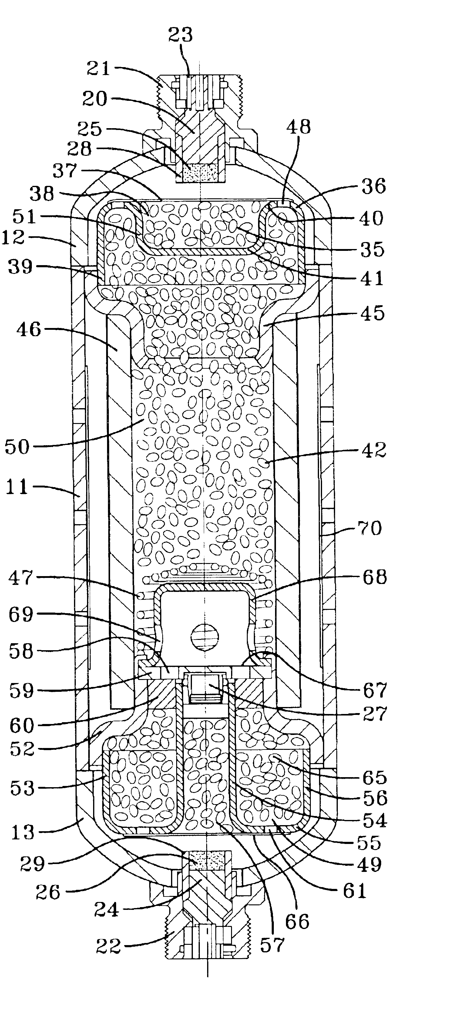
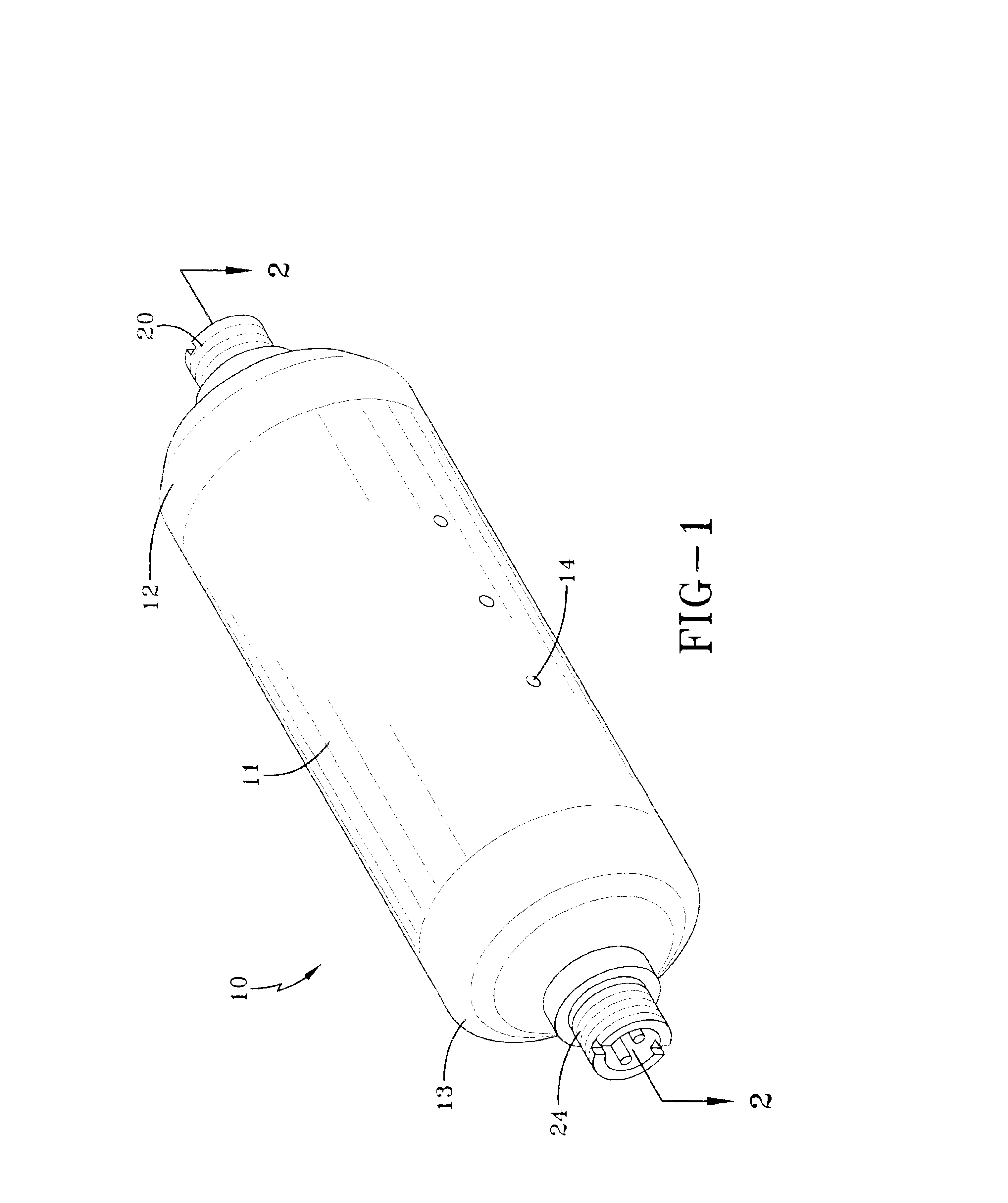
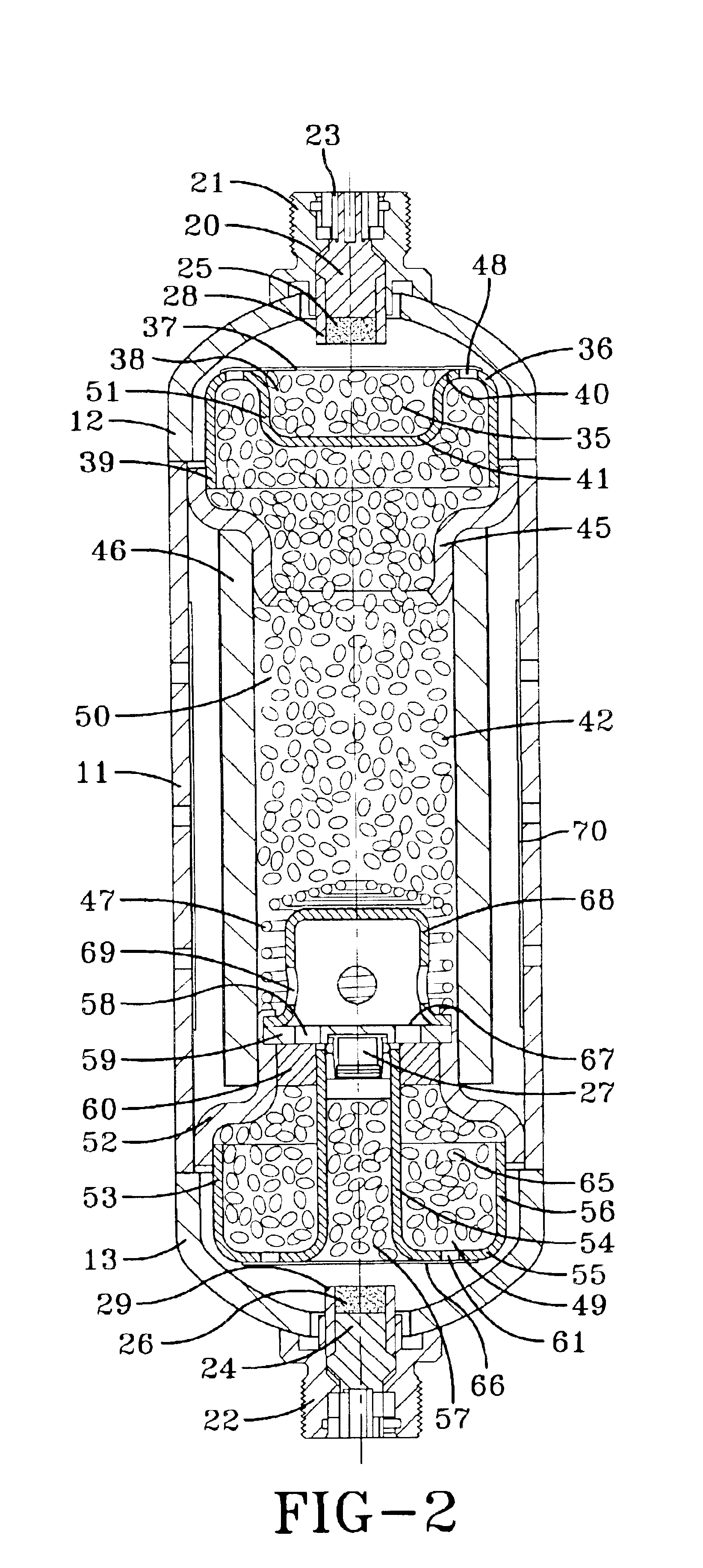
An inflator in accordance with the present invention is represented in FIG. 1. The inflator is a dual stage inflator 10 capable of providing multiple inflation rates for a vehicle airbag. The inflator 10 has a generally cylindrical shape having an elongated housing 11 with a first endcap 12 connected on one end of the housing 11 and a second endcap 13 connected on the other end of the housing 11. The housing 11 and the endcaps 12, 13 are made from a metallic material such as steel, low carbon steel, aluminum, a metal alloy, and the like. The endcaps are connected with the housing 11 by welding. The housing 11 contains a plurality of exit ports 14 arranged around the circumference thereof. The inflation gas is able to exit the inflator 10 via the exit ports 14 and travel into a folded airbag (not shown) to inflate the folded airbag. The exit ports 14 are arranged in a manner so that the inflator 10 is thrust neutral as inflation gas escapes the inflator 10. It is understood that the ...


PUM

PropertyMeasurementUnit
temperatureaaaaaaaaaa
melting pointaaaaaaaaaa
autoignition temperatureaaaaaaaaaa

Abstract

A dual stage invention is designed to autoignite an autoignition material before a low temperature gas generant melts. Low temperature gas generants include a high nitrogen content organic fuel with ammonium nitrate as the oxidizer. The dual stage inflator has a first gas generant and a second gas generant that are ignited by separate igniters. The first gas generant and the second gas generant are insulated from the inflator housing to delay the heat transfer from the housing to the first gas generant and second gas generant during a bonfire test, which needs to be passed to receive Department of Transportation classification. The dual stage inflator also has an autoignition cartridge for disposing of the second gas generant by the first gas generant after the first gas generant burns for a predetermined amount of time.

Description

FIELD OF THE INVENTIONThe present invention relates to an inflator for providing inflation gas to fill an inflatable restraint cushion, and particularly relates to a dual stage inflator capable of tailoring inflation gas output based upon crash severity in addition to size and / or position of a vehicle occupant.BACKGROUND OF THE INVENTIONInflatable restraint cushions are commonly installed in motor vehicles to reduce the likelihood of the vehicle occupants sustaining injuries during vehicle crashes. Inflatable restraint cushions are commonly known as airbags in the safety restraint industry. During a vehicle crash, an airbag is rapidly filled with inflation gas between the vehicle occupant and the interior of the vehicle. The airbag absorbs the vehicle occupant's kinetic energy to provide a controlled, reduced deceleration of the vehicle occupant and to prevent the vehicle occupant from contacting the hard surfaces of the vehicle interior.The source of inflation gas for an airbag is ...

Claims


Application Information

Patent Timeline
Patent Type & Authority Patents(United States)
IPC IPC(8): F42B3/00F42B3/04B60R21/26B60R21/264
CPCB60R21/2644F42B3/04B60R2021/2648B60R2021/2633B60R21/2334B60R2021/26076B60R2021/26011
Inventor KELLEY, MICHAEL EUGENECURTIS, ANTHONY J.MULVILLE, MICHAEL FELIXTREVILLYAN, DENNIS A.FITZGERALD, KEVIN
Owner KEY SAFETY SYST
Learn More