
Tape medium running device

a running device and tape medium technology, applied in the direction of speed-changing/reversing arrangements, recording information storage, instruments, etc., can solve the problems of inability to reduce, damage to magnetic recording tapes, and tape may be cut, so as to reduce fluctuations in sensitivity

Inactive Publication Date: 2005-02-08
PANASONIC CORP
View PDF7 Cites 8 Cited by
  • Summary
  • Abstract
  • Description
  • Claims
  • Application Information

AI Technical Summary

Benefits of technology

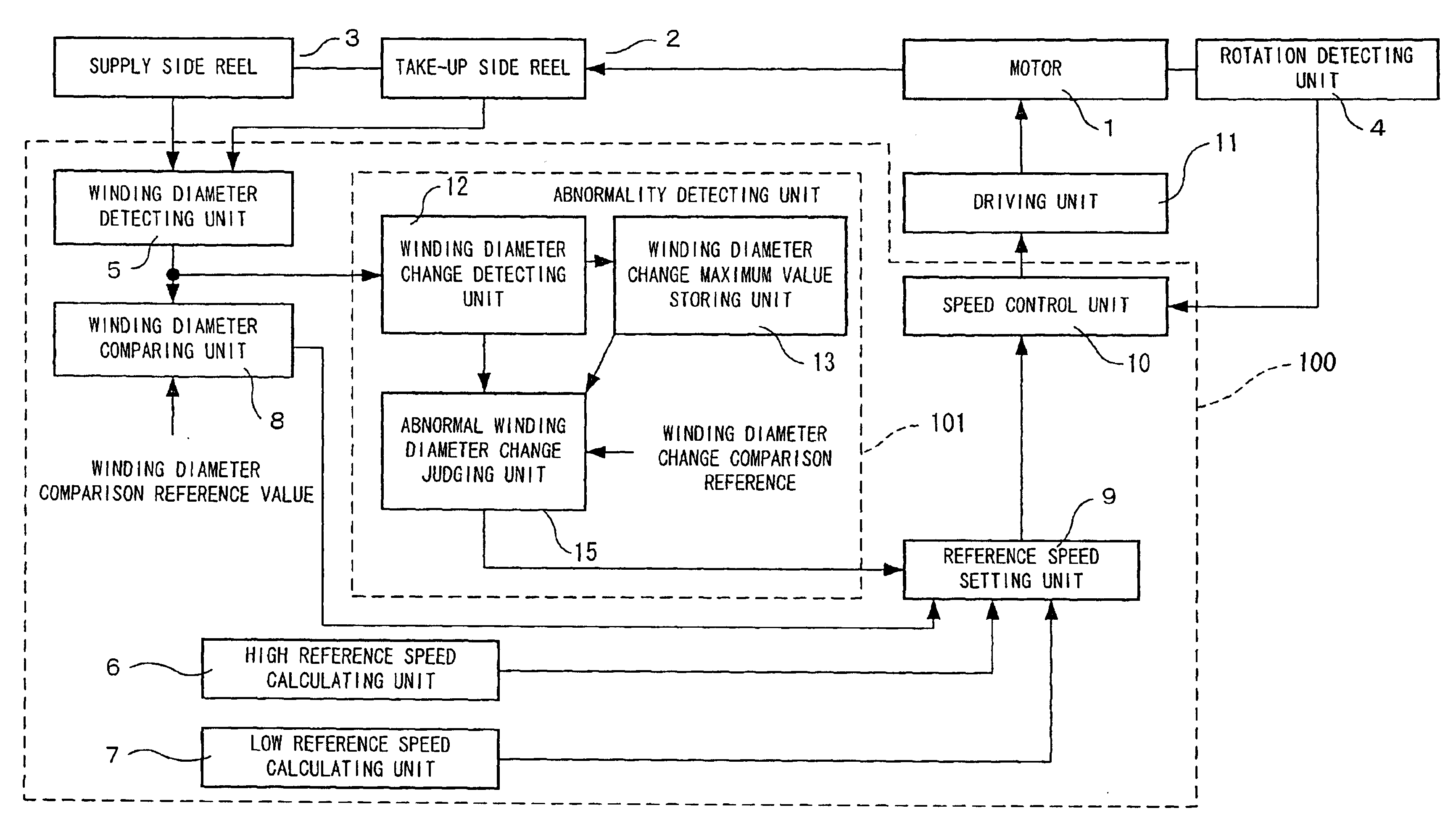
"The present invention is a tape medium running device that reduces the risk of damage to the magnetic recording tape and reduces the time required for fast forwarding and rewinding. The device includes an abnormality detecting unit that detects abnormal changes in the winding diameter of the tape, such as erroneous detection of the winding diameter. The device also includes a reference speed setting unit that adjusts the rotation speed of the motor based on the detected winding diameter and a comparison reference value. The device can detect abnormal changes in the winding diameter and quickly respond to them, preventing damage to the tape and reducing the time required for fast forwarding and rewinding."

Problems solved by technology

In the event of such abnormality, the tape may be cut.
Thus, reduction cannot be performed to the second speed and an approach is made to the end of the magnetic recording tape while the high speed (first speed) is maintained, resulting in a damage on the magnetic recording tape.
. . , when such erroneous detections of winding diameters successively occur until the end of the magnetic recording tape, a deceleration point cannot be correctly detected.

Method used


Image

  • Tape medium running device
  • Tape medium running device
  • Tape medium running device

Examples


embodiment 1

(Embodiment 1)

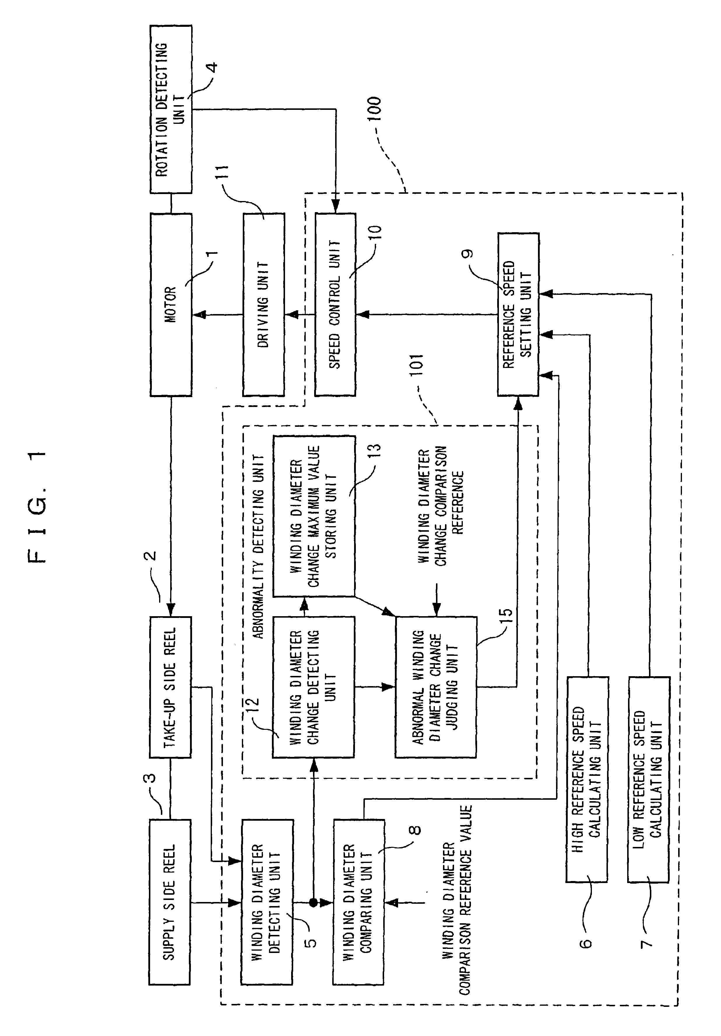
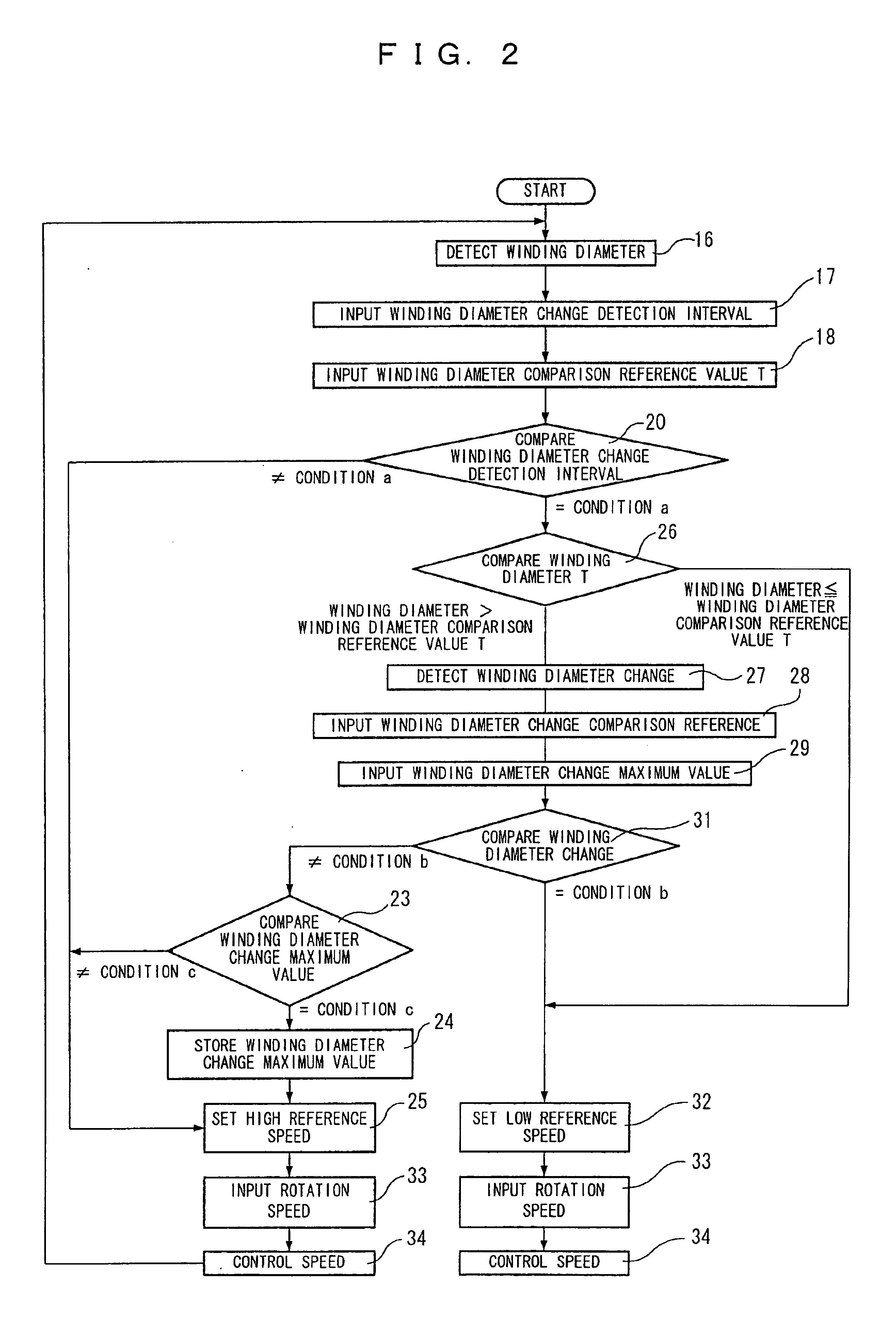
FIGS. 1 to 3 show (Embodiment 1) of the present invention.

FIG. 1 shows a tape medium running device according to (Embodiment 1) of the present invention. The same constituent elements as those of the conventional art are indicated by the same reference numerals and the description thereof is omitted.

In FIG. 1, an abnormality detecting unit 101 is constituted by a winding diameter change detecting unit 12, a winding diameter change maximum value storage 13, and an abnormal winding diameter change judging unit 15. In the present embodiment, the functions surrounded by a broken line are realized while a microcomputer 100 serves as a main part.

The winding diameter change detecting unit 12 detects output from a winding diameter detecting unit 5 every unit time that is predetermined in the winding diameter change detecting unit 12, detects a change in winding diameter per unit time, and outputs the change.

The winding diameter change maximum value storage 13 stores and output...

embodiment 2

(Embodiment 2)

FIGS. 4 to 6 show a tape medium running device according to (Embodiment 2) of the present invention. In FIGS. 4 to 6, the same constituent elements as those of the conventional art are indicated by the same reference numerals and the description thereof is omitted.

An abnormal winding diameter change judging unit 15 of (Embodiment 1) judges whether a winding diameter detected by a winding diameter detecting unit 5 is correct or not based on a value outputted from a winding diameter change maximum value storage 13, a value outputted from a winding diameter change detecting unit 12, and a winding diameter change comparison reference which has been inputted in advance, the output from the abnormal winding diameter change judging unit 15 being used as an output signal transmitted from an abnormality detecting unit 101 to a reference speed setting unit 9, and the winding diameter change comparison reference inputted to the abnormal winding diameter change judging unit 15 is ...

embodiment 3

(Embodiment 3)

FIGS. 7 to 9 show (Embodiment 3) of the present invention.

FIG. 7 shows a tape medium running device according to (Embodiment 3) of the present invention. The same constituent elements as those of the conventional art are indicated by the same reference numerals and the description thereof is omitted.

A single winding diameter comparison reference value is set in the winding diameter comparing unit 8 of (Embodiment 1). On the other hand, in (Embodiment 3), three winding diameter comparison reference values are set and proper one of the three reference values and the output from the winding diameter detecting unit 5 are compared with each other. Further, while a signal is not inputted from a winding diameter comparing unit 8 to a winding change detecting unit 12 of an abnormality detecting unit 101 in (Embodiment 1), (Embodiment 3) is different from (Embodiment 1) only in that a signal is inputted to an abnormality detecting unit 101 from a winding diameter comparing unit...


PUM

PropertyMeasurementUnit
winding diameteraaaaaaaaaa
frequencyaaaaaaaaaa

Abstract

A tape medium running device which can more correctly detect erroneous detection of a winding diameter, prevent an approach from being made to the end of the magnetic recording tape at high running speed and causing a damage on the tape, and can shorten fast forwarding / rewinding time. In this device, a winding diameter change detecting unit detects a change in winding diameter, and a ratio of a detected change in diameter and a maximum value of changes in winding diameter having been detected previously is compared with a predetermined winding diameter change comparison reference to detect abnormality. Thus, it is possible to prevent any approach from being made to the end of the magnetic recording tape at a high running speed based on an erroneous detection to causing a damage on the tape, and to shorten time for fast forwarding and rewinding.

Description

FIELD OF THE INVENTIONThe present invention relates to a tape medium running device for performing high-speed running that is installed in a magnetic recording / reproducing apparatus such as a cassette video tape recorder using a magnetic recording medium in the form of a tape.BACKGROUND OF THE INVENTIONIn recent years, following the growth of disks having an advantageous access speed as recording / reproducing mediums, it has been demanded to increase the winding speed of a tape and shorten fast forwarding / rewinding time to improve usability, by increasing the rotation speed of a motor of a magnetic recording tape which has a disadvantageous access speed.As a tape medium running device, devices disclosed in Japanese Unexamined Patent Publication No. 2000-215559 and so on have been known. FIG. 10 shows a conventional tape medium running device.Reference numeral 1 denotes a motor for driving a tape, reference numeral 2 denotes a take-up side reel where one end (beginning or end) of a ma...

Claims


Application Information

Patent Timeline
Patent Type & Authority Patents(United States)
IPC IPC(8): G11B15/05G11B15/06G11B15/26G11B15/44
CPCG11B15/06G11B15/44G11B15/26
Inventor TANABE, NAOHISANAKAMURA, KENJIRO
Owner PANASONIC CORP
Learn More