Pipe-coupling device

a technology of pipe coupling and pipe thread, which is applied in the direction of fluid pressure sealing joints, hose connections, mechanical devices, etc., can solve the problems of reducing requiring a lot of time for processing screw threads, and unable to make the edge of the pressing member bite into the pipe by means of the pressing force of the coil spring alone, etc., to achieve convenient handling, reduce the number of parts, and reduce the cost

Inactive Publication Date: 2005-02-08
HAKKO CO LTD
View PDF12 Cites 78 Cited by
  • Summary
  • Abstract
  • Description
  • Claims
  • Application Information

AI Technical Summary

Benefits of technology

In this case, if the core member came out of the locknut member, the locking members would also drop out of the locknut member together with the core member. In this respect, the pipe-coupling sub-assembly of the present invention may preferably comprise an inner peripheral groove formed in the locknut member between the internal threads and the internal conical surface, and a stopper ring fitted in the inner peripheral groove. Due to this stopper ring, the core member can be prevented from coming out of the locknut member in the axial direction, thus enabling convenient handling of this sub-assembly as a single component.
In place of the stopper ring, the core member may be provided with a claw portion in the outer periphery thereof to project outwardly in radial direction. The claw portion fits in the inner peripheral groove of the locknut member such that the core member is prevented from dropping out of the locknut member in the axial direction. In this case, since it is not necessary to prepare additional parts like the stopper ring, the number of parts is reduced, resulting in a lower cost.

Problems solved by technology

However, in this coupling operation, the external threads should necessarily be formed at the end of the pipe beforehand, which requires a lot of time for processing the screw threads and for the connecting operation of the pipes in situ.
Although the coil spring is arranged between the female body and the inner collar, the pressing force of the spring is too weak to make the pressing member strongly engage with the outer periphery of the pipe.
However, if the pipe is made of hard resin or metal, it is impossible to make the edge of the pressing member bite into the pipe by means of the pressing force of the coil spring alone.
As a result, the pipe joint fails to prevent the pipe from withdrawal.

Method used


Image

  • Pipe-coupling device
  • Pipe-coupling device
  • Pipe-coupling device

Examples


second embodiment

FIG. 9 shows the present invention.

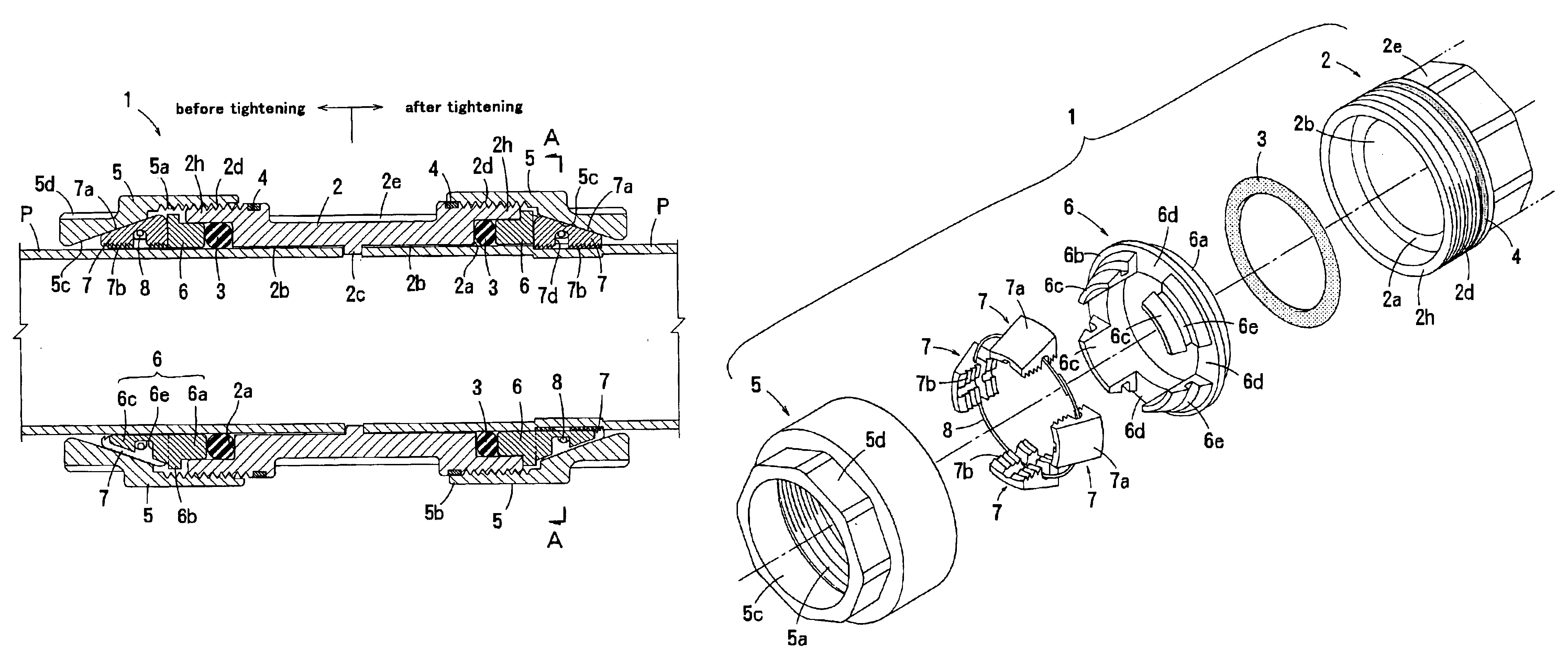
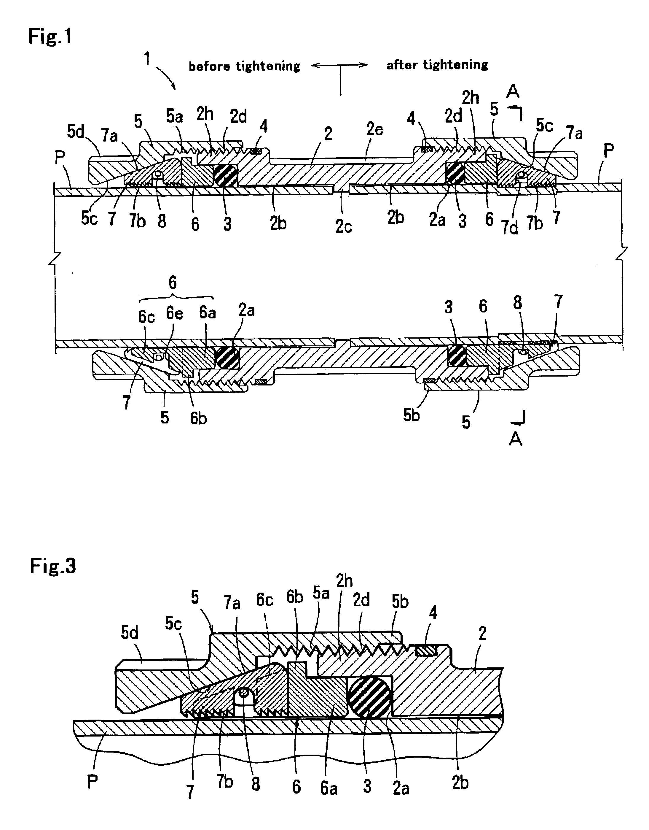
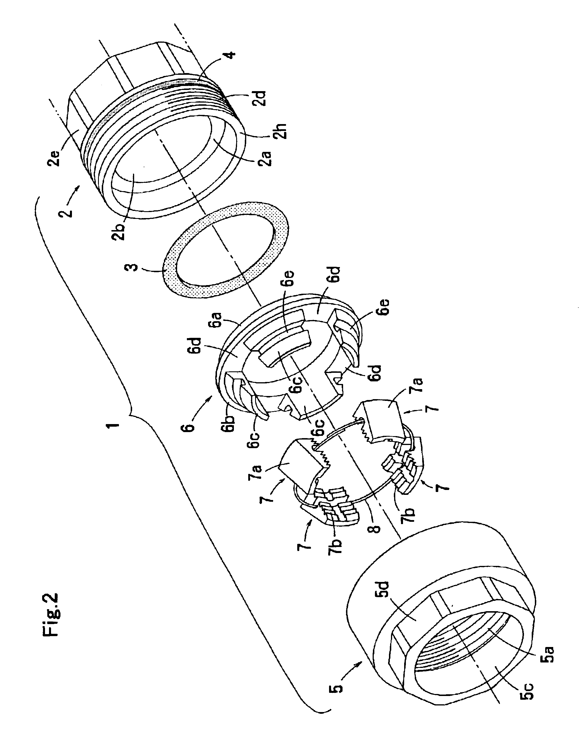
In this embodiment, the joint body 2 consists of a tubular body 2A and two sleeves 2B that are rotatably mounted on the outer periphery of the tubular body 2A on the both openings 2h. Each of the sleeves 2B has, in its outer periphery, external threads 2d to be engaged with the locknut 5. The pipe joint according to this embodiment is similar in structure to the pipe joint 1 according to the first embodiment except the joint body 2 (2A and 2B). Therefore, parts of the second embodiment identical to those of the first embodiment are denoted by the same reference numerals, to omit redundant description.

The outer periphery of the tubular body 2A and the inner periphery of the sleeve 2B have circumferential grooves 10 and 11 respectively at positions opposing to each other to form a circumferential space. A stopper ring 12 made of a split ring is inserted in this circumferential space so as to prevent the sleeve 2B from sliding in the axial direction w...

fourth embodiment

FIGS. 15 and 16 show the pipe joint according to the present invention.

In this embodiment, the core member 6, the locking members 7 and the wire 8 are attached into the locknut 5 to form a sub-assembly. Therefore, instead of the stopper ring 15 employed in the third embodiment, a claw portion 6h is integrally formed in the outer periphery of the core member 6 projecting outwardly in radial direction. The claw portion 6h engages with the inner peripheral groove 5e of the locknut 5 so as to prevent the core member 6 from dropping off in the axial direction freely. Preferably, the core member 6 in this embodiment is made of resin. Since the claw portion 6h can deflect radially, the core member 6 can be smoothly inserted into the locknut 5.

According to this embodiment, an inner flange 5f, which protrudes radially inwardly beyond the internal conical surface 5c, is formed in the inner surface of the locknut 5 at its one end in the axial direction. The inner flange 5f prevents the locking...


PUM

PropertyMeasurementUnit
diameteraaaaaaaaaa
thicknessaaaaaaaaaa
resilient forceaaaaaaaaaa

Abstract

A pipe-coupling device comprises a joint body having an opening with external threads to receive a pipe, a locknut having internal threads engaged with the external threads of the joint body, an annular core member disposed within the locknut, and a plurality of locking members retained in apertures of the core member to be spaced circumferentially apart from each other. Upon tightening rotation of the locknut around the joint body, the internal conical surface of the locknut slidably contacts with the conical surfaces of the locking members so as to press the locking members radially inwardly, to cause the gripping portions of the locking members come into gripping engagement with the outer periphery of the inserted pipe, thereby strongly preventing withdrawal of the pipe from the joint body even when the pipe is made of hard material.

Description

FIELD OF THE INVENTIONThe present invention relates to a pipe-coupling device, such as a pipe joint that can be used for joining together ends of pipes, e.g., water supply pipes.BACKGROUND OF THE INVENTIONGenerally, a pipe joint having internal threads is used for joining together ends of pipes, e.g. water pipes laid under the ground. In those cases, the pipe has external threads formed at the end thereof (in advance), so that the pipe can be coupled by engaging the external threads of the pipe with the internal threads of the pipe joint. However, in this coupling operation, the external threads should necessarily be formed at the end of the pipe beforehand, which requires a lot of time for processing the screw threads and for the connecting operation of the pipes in situ.In order to solve the above-described problem, the Japanese patent application publication JP10-122460A discloses a pipe joint that comprises a female body, an outer collar, an inner collar, a pressing member, and ...

Claims


Application Information

Patent Timeline
Patent Type & Authority Patents(United States)
IPC IPC(8): F16L19/00F16L19/08
CPCF16L19/086F16L19/075F16L47/04
Inventor MINAMI, MASAFUMI
Owner HAKKO CO LTD
Why Eureka
Try Eureka