Mold tool clamping device for blow mold machines

Inactive Publication Date: 2005-02-08
HESTA GRAHAM
View PDF8 Cites 15 Cited by
  • Summary
  • Abstract
  • Description
  • Claims
  • Application Information

AI Technical Summary

Benefits of technology

It is thus the task of the invention, to provide a tool clamping device, which makes possib

Problems solved by technology

This type of securing is frequently tedious, since the intermediate space between the rear clamp plate and machine frame is difficul

Method used


Image

  • Mold tool clamping device for blow mold machines
  • Mold tool clamping device for blow mold machines
  • Mold tool clamping device for blow mold machines

Examples


Embodiment Construction

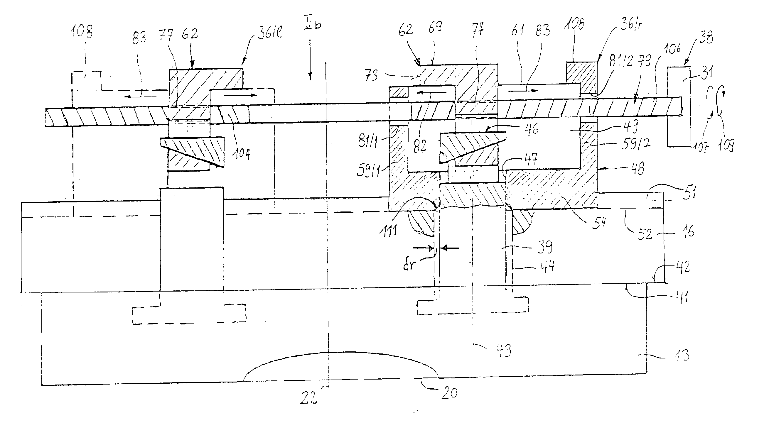
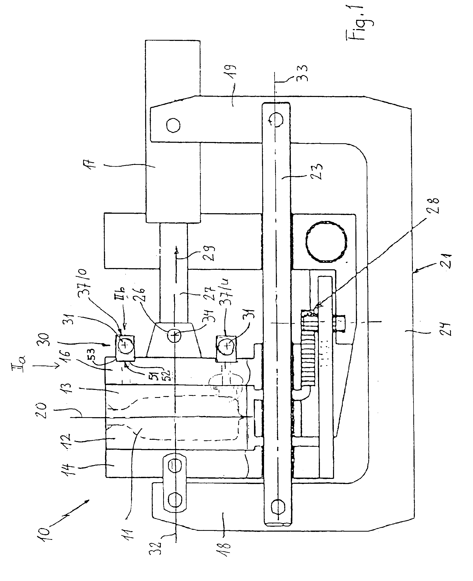
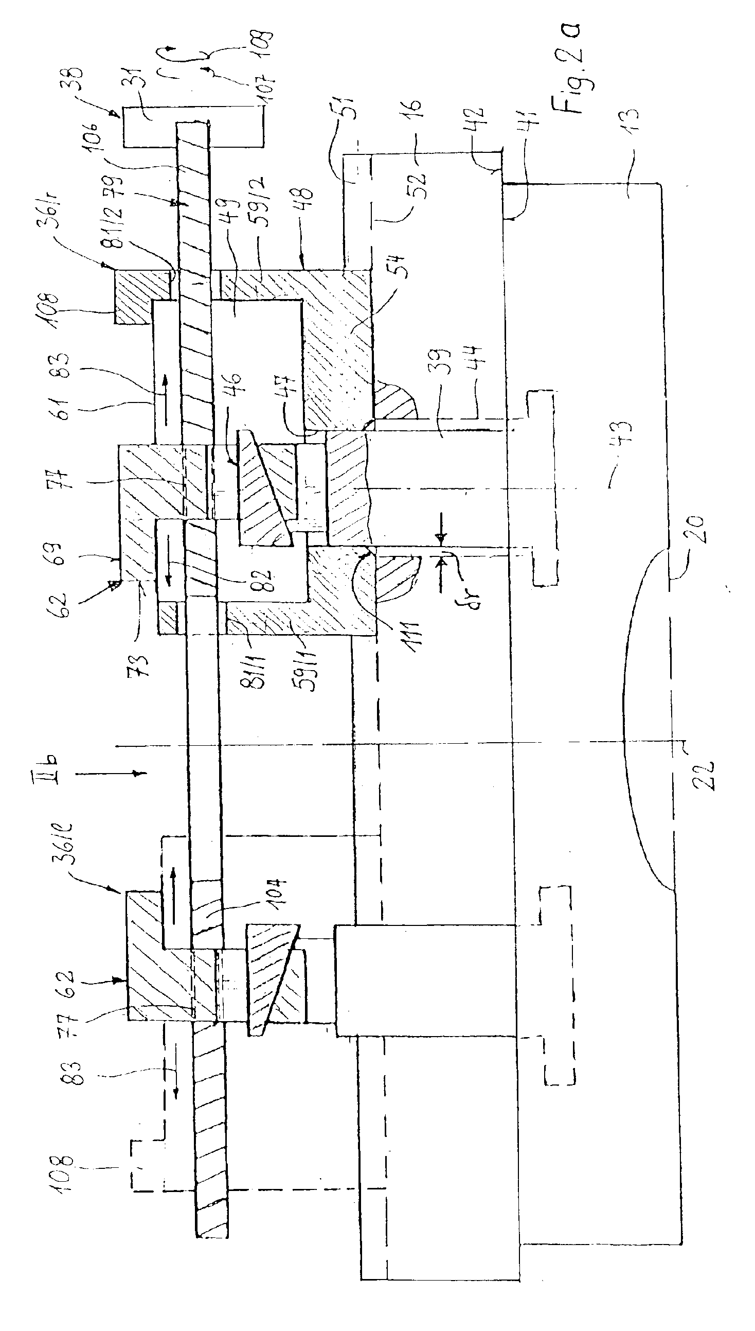
The locking system indicated overall with reference number 10 in FIG. 1 represents a blow mold machine with which for example bottle shaped mold hollow bodies 11 can be blown. The blow mold provided therefore includes two mold halves—mold tools 12 and 13—, which are respectively secured to one clamping plate 14 or as the case may be 16. They can be pushed into the represented closed configuration of the blow mold by control of a hydraulic cylinder 17 of the lock system 10, wherein the two mold tools 12 and 13 lie against each other along a vertical longitudinal central plane 20, which is the common longitudinal central plane of a—not shown—blow station and a—likewise not shown—extrusion station of the blow mold machine, between which the blow mold carrying locking system 10 for receiving extruded tube shaped plastic pre-forms, as well as, and for blowing the mold hollow bodies back and forth is moveable.

The mold tool 12 and 13 carrying clamp plates 14 and 16 are provided between ver...


PUM

PropertyMeasurementUnit
Angleaaaaaaaaaa
Diameteraaaaaaaaaa
Displacementaaaaaaaaaa

Abstract

A mold tool clamping device (30) for a blow mold comprising two mold halves (13 and 13). For fixing of the rear blow mold half to the clamp plate associated therewith, there is provided at least two wedge locks or cam locks, which are provided in a symmetric arrangement relative to the “vertical” transverse central plane of the rear mold tool, which are clampable with wedges, which, supported on the back side of the clamp plate, transverse to the longitudinal axis of the clamp bolts, are drivable into their anchor groove of anchor keyways, wherein these wedge locks are so arranged, that the wedges are drivable “from the side” into their clamp position in designed “grooves” of the clamp bolts complimentary thereto. This makes possible a rapid and positionally accurate securing of the rear mold half to its rear clamp plate.

Description

BACKGROUND OF THE INVENTION1. Field of the InventionThe invention concerns a mold tool or segment clamping device for blow mold machines, in which a blow mold comprising two mold halves—mold tools—, which can be pushed together via a closure driver or actuator, in such a manner, that in the closed configuration of the blow mold they lie directly against each other along a central plane and are again separable from each other “symmetric to this central plane”, wherein as the closure actuator an electric or hydraulic linear actuator is provided, which engages on the “back” side of the clamp plate facing the drive and the further aggregates of the machine carrying machine frame, which clamp plate is synchronized via a synchronization drive with the “front” clamp plate on which the “front” mold tool is tightly clamped, is synchronized, the synchronization being in such a manner, that both mold halves are displaceable by a defined stroke relative to the blow mold central plane, and where...

Claims


Application Information

Patent Timeline
IPC IPC(8): B29C49/56B29C49/42
CPCB29C49/42B29C49/56B29C2049/4856B29C2049/4864B29C49/561
Inventor EFFENBERGER, ALFRED
Owner HESTA GRAHAM
Why Eureka
Try Eureka