
Medical knife assembly and method of using same

a technology of medical knife and clamping mechanism, which is applied in the field of cutting and clamping mechanism, can solve the problems of increased risk of accidents, slippery gloves of obstetricians, etc., and achieve the effect of preventing or at least greatly reducing the flow of blood

Inactive Publication Date: 2005-02-08
MEDICAL DEVICES GROUP
View PDF15 Cites 49 Cited by
  • Summary
  • Abstract
  • Description
  • Claims
  • Application Information

AI Technical Summary

Benefits of technology

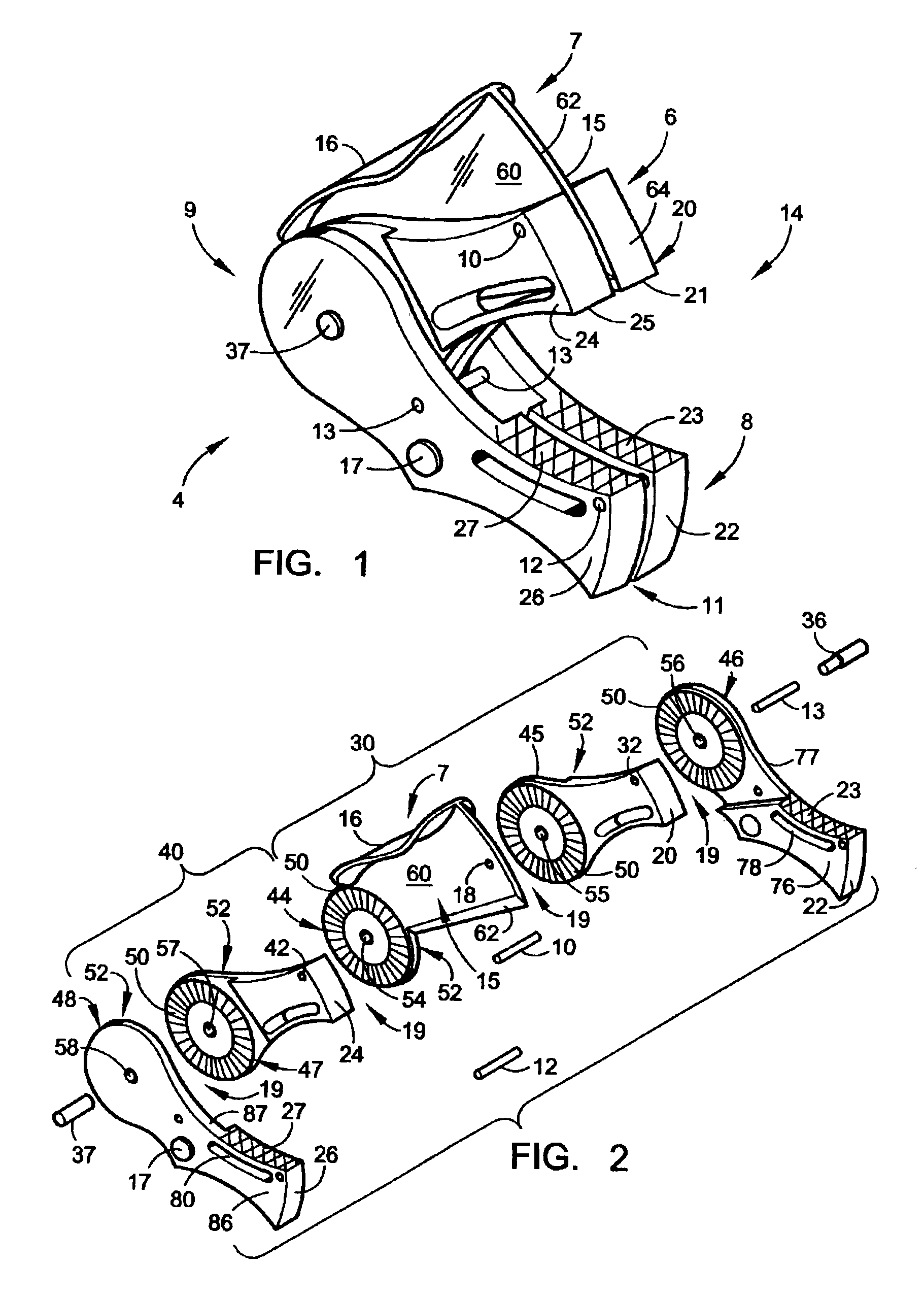
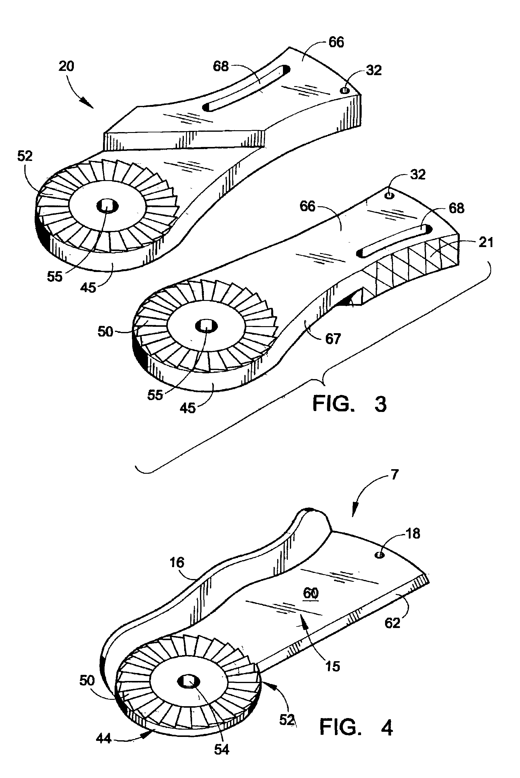
A medical knife assembly includes an outer clamp assembly and an inner clamp blade assembly having a cutting blade assembly. The inner and outer clamp assemblies are pivotally connected at about their proximate ends so they may be squeezed together with one hand to affect a novel method of clamping and cutting in a single motion operation. A set of shear pins holds the component parts of the inner and outer assemblies together in a ready position that enables a user to properly position the knife assembly for severing an umbilical cord at the time of birth. Once the umbilical cord is severed, the component parts of the inner and outer assemblies separate providing independent clamps, one staying with an infant segment of the umbilical cord and one staying with a maternal segment of the umbilical cord. The two independent clamps operate to clamp the umbilical cord on both sides of the cutting blade assembly thereby preventing or at least greatly reducing the flow of blood from around the clamps at the time of severance.

Problems solved by technology

Such fluids on the gloved hands of the obstetrician become very slippery and thereby increased risk of an accident, such as the possibility of the obstetrician dropping the infant as the infant is moved away from the mother.

Method used


Image

  • Medical knife assembly and method of using same
  • Medical knife assembly and method of using same
  • Medical knife assembly and method of using same

Examples


Embodiment Construction

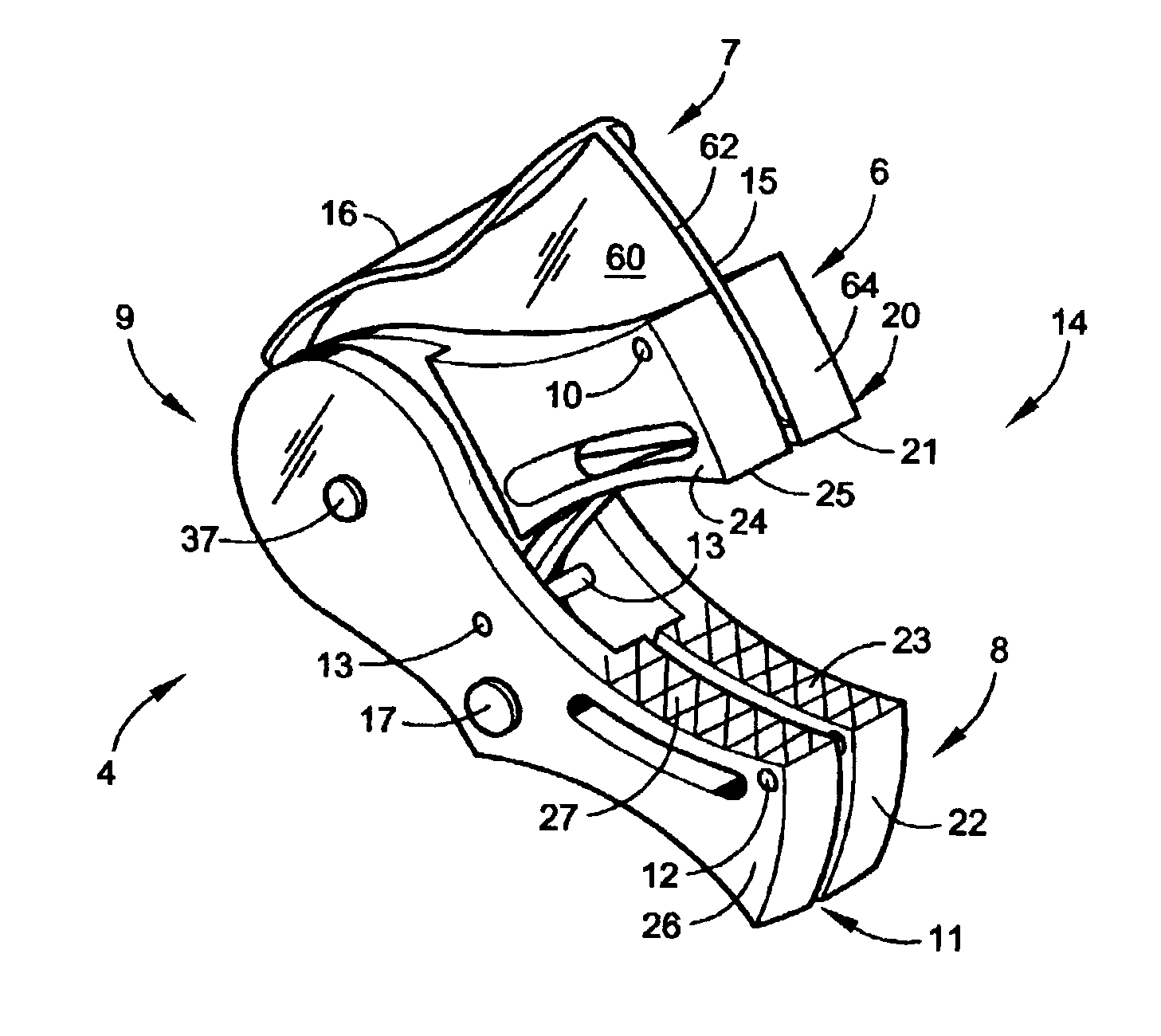
Referring now to the drawings and more particularly to FIG. 1 thereof, there is illustrated a disposable medical knife assembly 4, which is constructed in accordance with the present invention. The knife assembly 4 is designed specifically for clamping and severing an umbilical cord with one simple motion with a consistent predetermined amount of hand pressure force of between about ten pounds of pressure and about twelve pounds of pressure which insures precise cutting as will be explained hereinafter in greater detail. The size of the disposable knife assembly 4 is specifically designed to fit any size of umbilical cord and to be easily held in one hand to affect a novel method of clamping and cutting in a single motion operation. More specifically this specification will describe a medical knife assembly 4 that is designed to sever the umbilical cord by clamping the umbilical cord on both the fetal and the maternal side and simultaneously cutting the cord. The knife assembly 4 as...


PUM


Abstract

A medical knife assembly includes an outer clamp assembly and an inner clamp blade assembly having a cutting blade assembly. The inner and outer clamp assemblies are pivotally connected at about their proximate ends so they may be squeezed together with one hand to affect a novel method of clamping and cutting in a single motion operation. A set of shear pins holds the component parts of the inner and outer assemblies together in a ready position that enables a user to properly position the knife assembly for severing an umbilical cord at the time of birth. Once the umbilical cord is severed, the component parts of the inner and outer assemblies separate providing independent clamps, one staying with an infant segment of the umbilical cord and one staying with a maternal segment of the umbilical cord. The two independent clamps operate to clamp the umbilical cord on both sides of the cutting blade assembly thereby preventing or at least greatly

Description

FIELD OF INVENTIONThis invention relates to a cutting and clamping mechanism, and more particularly to a cutting and clamping mechanism for use in obstetrics for severing and clamping an umbilical cord.BACKGROUND OF INVENTIONCutting assemblies are well known in the art. For example, reference may be made to the following U.S. patent documents: U.S. Pat. Nos. 3,631,858; 4,716,886; 4,938,215; 5,046,252; 5,190,556; 5,584,840; 5,667,516; 5,676,672; 5,913,862; 5,937,523; 5,968,054; and 5,997,548.The severance of an umbilical cord occurs shortly after birth. The umbilical cord functions to provide a fetus with oxygen and nutrients during the gestation period. Once a child has been born, the umbilical cord needs to be severed. In the regard, an obstetrician, or other practitioner tends to this task by first clamping the cord to reduce blood flow and then severs the cord, thus freeing the fetus from the mother. At the moment before the umbilical cord is severed, it is engorged with blood un...

Claims


Application Information

Patent Timeline
IPC IPC(8): A61B17/122A61B17/12A61B17/32A61B17/42
CPCA61B17/122A61B2017/1225A61B17/42A61B17/32
Inventor ORLOWSKI, BOGUSLAW
Owner MEDICAL DEVICES GROUP
Learn More