Air cleaner and resonator assembly

a resonator and air cleaner technology, applied in the field of engine air cleaners, can solve the problems of poor performance, dust, dirt, other particulate contaminants in the air drawn into the air induction system, and engine noise propagated back through the air induction components, and achieve the effect of reducing the overall number of required components and being easy to assembled

Inactive Publication Date: 2005-02-08
SIEMENS VDO AUTOMOTIVE INC
View PDF2 Cites 11 Cited by
  • Summary
  • Abstract
  • Description
  • Claims
  • Application Information

AI Technical Summary

Benefits of technology

to provide a simplified air cleaner and resonator assembly that reduces the overall number of required components, and which can be easily assembled, as well as overcoming the other above-mentioned deficiencies with the prior art.

Problems solved by technology

For example, engine noise is propagated back through the air induction components, which is undesirable.
Another undesirable side effect introduced by air induction components, is that the air that is drawn into the air induction system includes dust, dirt, and other particulate contaminants.
These contaminants can clog the engine resulting in poor performance.
The use of these additional components such as the resonator and air cleaner increases material and overall system costs.
Further, the assembly of the additional components into the air induction system is time consuming and labor intensive.

Method used


Image

  • Air cleaner and resonator assembly
  • Air cleaner and resonator assembly
  • Air cleaner and resonator assembly

Examples


Embodiment Construction

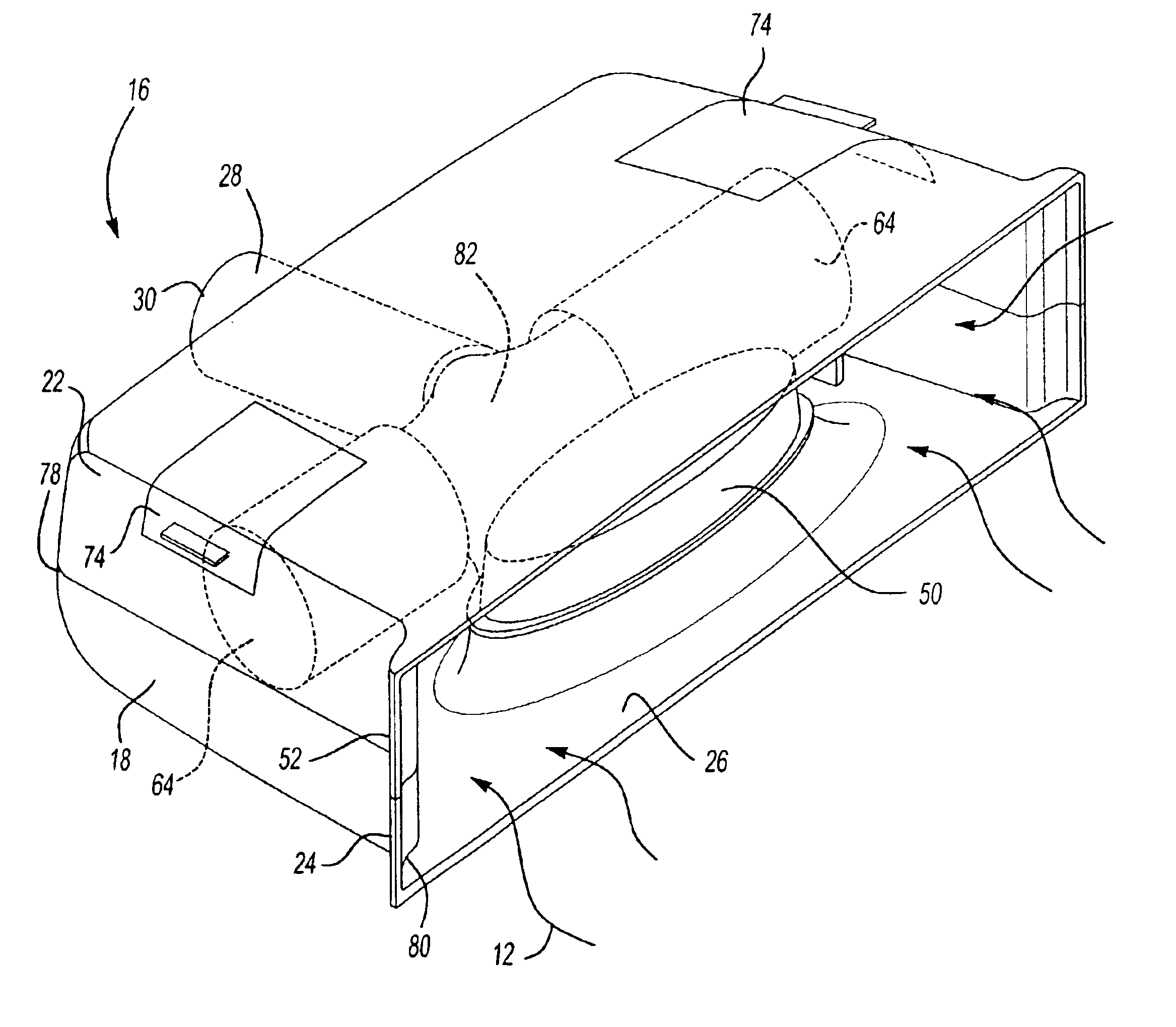
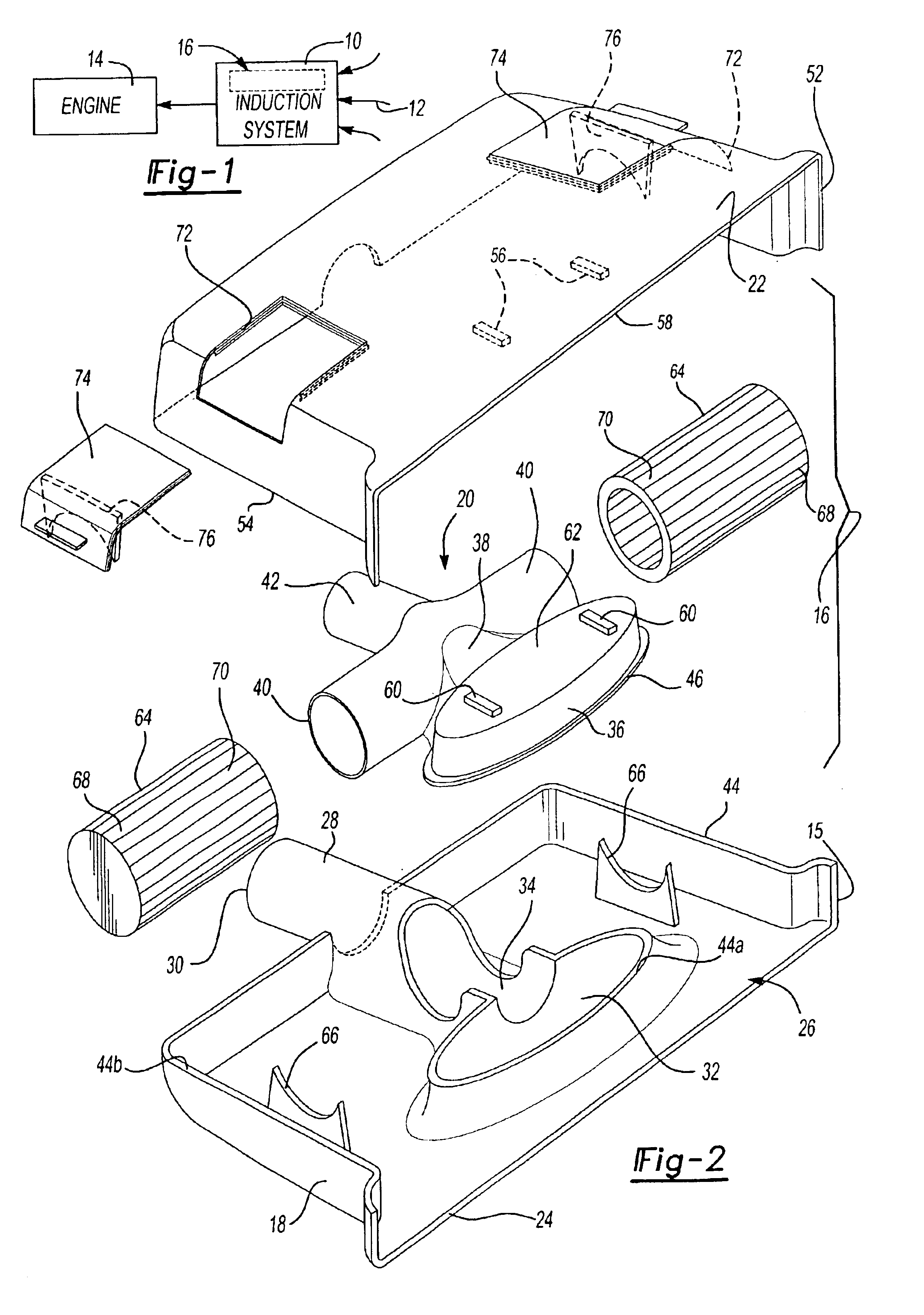
As shown in FIG. 1, an induction system 10 draws air 12 into a vehicle engine 14. In order to ensure that the engine 14 operates quietly and efficiently, the induction system 10 includes a resonator and air filter assembly, shown generally at 16.

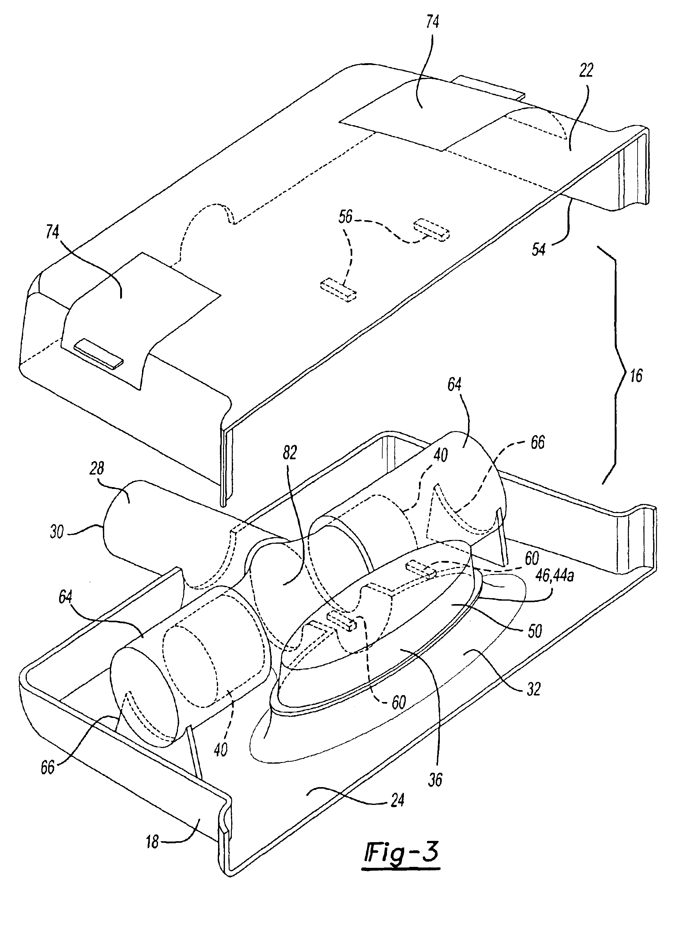
The resonator and air filter assembly 16 is shown in greater detail in FIG. 2. The resonator and air filter assembly 16 includes a lower shell 18, a middle shell 20, and an upper shell 22. The lower shell 18 includes a lower mouth portion 24 that forms an air inlet 26, and an exit tube 28 that forms an air outlet 30 to the engine 14. The lower shell 18 also includes a lower resonator portion 32 and a lower neck portion 34 that interconnects the lower resonator portion 32 to the exit tube 28.

The middle shell 20 includes an upper resonator portion 36, an upper neck portion 38, and a pair of air filter mounting tubes 40. The middle shell 20 also includes a small upper portion 42 that forms a portion of the exit tube 28. The exit tube 28 and upp...


PUM

PropertyMeasurementUnit
strengthaaaaaaaaaa
stiffnessaaaaaaaaaa
perimeteraaaaaaaaaa

Abstract

An air cleaner and resonator assembly is formed from a lower shell portion and an upper shell portion that are joined together to define an interior cavity having an inlet through which air is drawn. An exit tube, formed within the lower shell portion, directs air from the inlet to the engine. A middle shell portion is positioned within the inter cavity and is joined to both the upper and lower shell portions. A lower portion of a resonator is molded into the lower shell portion and an upper portion of the resonator assembly is molded into the middle shell portion. The upper portion is aligned with the lower portion and the middle and lower shell portions are welded together to form a sealed resonator chamber that attenuates engine noise. The upper and lower shell portions are then welded together to form the air cleaner and resonator assembly. Air filters are installed within the interior cavity and are selectively accessible through movable covers installed in the upper shell portion. The air filters are mounted on tube mounts molded into the middle shell portion and rest on cradle mounts formed on the lower shell portion.

Description

BACKGROUND OF THE INVENTIONThis invention is directed to an engine air cleaner that includes an integrally formed resonator.Air induction systems are used to conduct air to internal combustion engines. The use of air induction systems has resulted in the need for additional vehicle system components to compensate for certain undesirable side effects generated by the connection of air induction components to the vehicle engine. For example, engine noise is propagated back through the air induction components, which is undesirable. To address this problem, noise attenuation components, such as resonators, have been utilized to reduce these noises.Another undesirable side effect introduced by air induction components, is that the air that is drawn into the air induction system includes dust, dirt, and other particulate contaminants. These contaminants can clog the engine resulting in poor performance. Air cleaners with filters are used to remove these contaminants from the airflow prio...

Claims


Application Information

Patent Timeline
Patent Type & Authority Patents(United States)
IPC IPC(8): F02M35/14
CPCF02M35/14F02M35/1255F02M35/0215F02M35/02483F02M35/1227
Inventor BLOOMER, STEPHEN FRANCIS
Owner SIEMENS VDO AUTOMOTIVE INC
Why Eureka
Try Eureka