Inductive position sensing switching device

a technology of position sensing and switching device, which is applied in the direction of circuit-breaking switch, mechanical control device, pulse technique, etc., can solve the problems of mechanical switch, mechanical switch, mechanical micro-switch and mechanical sliding contact, and mechanical switch that cannot operate without wear

Inactive Publication Date: 2005-02-08
ZF FRIEDRICHSHAFEN AG
View PDF9 Cites 13 Cited by
  • Summary
  • Abstract
  • Description
  • Claims
  • Application Information

AI Technical Summary

Benefits of technology

The object of the present invention is to provide a switching device or a position sensing switching device which overcomes the aforesaid disadvantage of the wear occurring with mechanical switch elements of a conventional mechanical switching device by using wearfree switching units. A further advantage of the present invention is to provide a position sensing switching device which permits reliable monitoring of the operational capability of the position sensing switching device and / or reliable sensing of a selected switched position.
is to provide a position sensing switching device which permits reliable monitoring of the operational capability of the position sensing switching device and / or reliable sensing of a selected switched position.
The position sensing switching device according to the invention comprises at least one switching unit and at least one activation unit, the switching unit reacting to a relative spacial displacement of the switching unit and of the activation unit with respect to one another by outputting switching signals (corresponding to the relative displacement). The difference between the position sensing switching device according to the invention and other position sensing switching devices known from the prior art is that the switching unit has been embodied as an inductive sensor unit and the activation unit has been embodied as an inductive damping unit.
A particular advantage of sensing the present invention is obtained using a position sensing switching device in which either one activation unit simultaneously activates two or more switching units or the position sensing switching device has at least two activation units and at least three switching units, at least two of the activation units simultaneously activating at least two of the switching units.
The method of operation of the position sensing switching devices according to the invention is clarified by the example in the following figures.

Problems solved by technology

However, a significant disadvantage of these switching devices is that they have mechanical switching units or mechanical microswitches and mechanical sliding contacts for generating switching signals.
The mechanical switches have the disadvantage that they do not operate without wear.
Their service life is limited, on the one hand, by material erosion of contacts, by changes in material (oxidation) and by deposition on the switching contacts which are caused by mechanical friction, electrical overloading or the occurrence of an arc during the switching-off or switching-over process.
The vibrations of the entire gate-type-gear changing unit also lead to increased wear of of the sliding contacts and sliding tracks of the mechanical sliding switches.

Method used


Image

  • Inductive position sensing switching device
  • Inductive position sensing switching device
  • Inductive position sensing switching device

Examples


Embodiment Construction

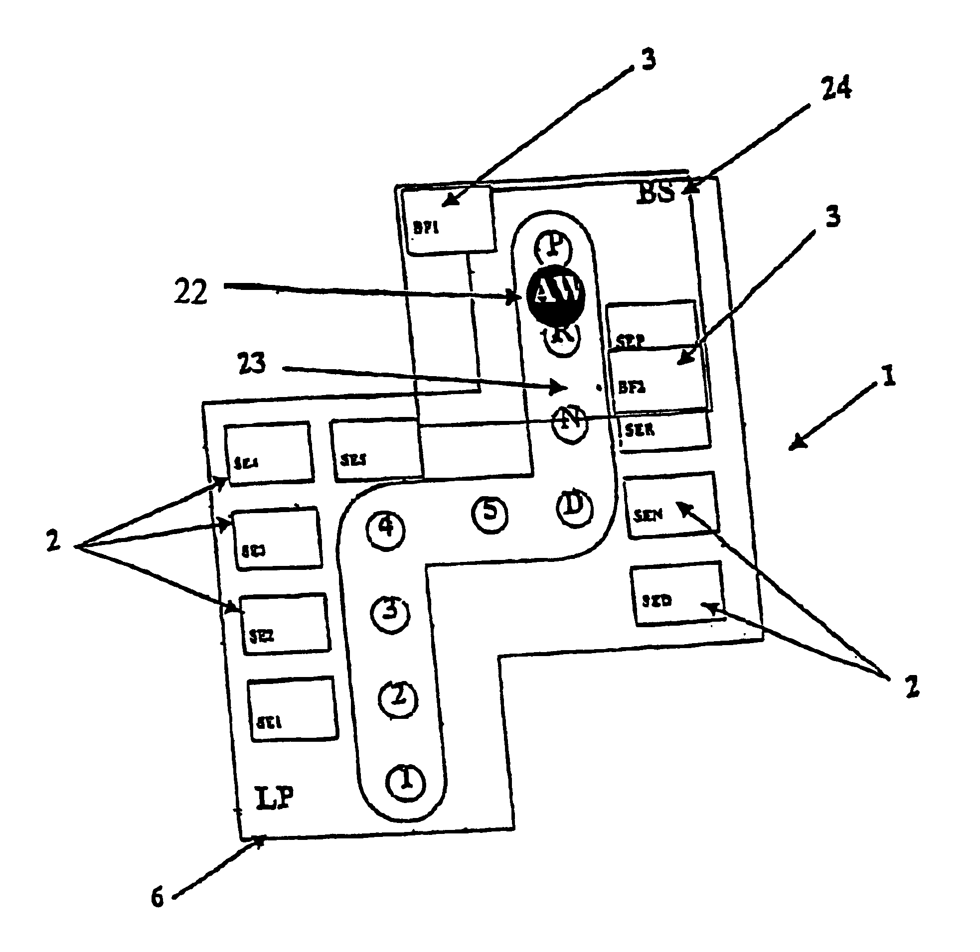
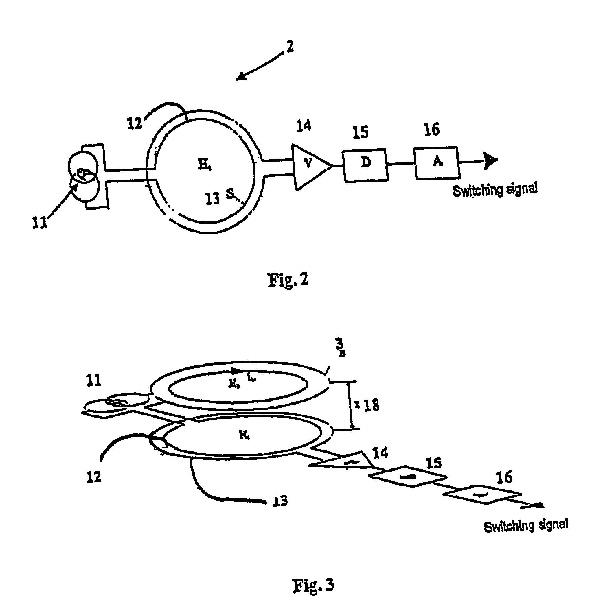
FIG. 1 is a general schematic view of a preferred embodiment of a position sensing switching device 1 according to the invention in the form of a gear-speed-changing unit for generating gear-speed-changing signals for an automatic gearbox. The position sensing switching device 1 has four switching units 2 and at least one activation unit 3., the activation unit 3 being displaceable with respect to the switching units 2. The relative displacement of the switching units 2 and of the activation unit 3 with respect to one another takes place both in the horizontal and vertical directions. Displacement movements are thus understood both to be a pure displacement movement and a tilting movement. The switching units 2 are embodied as inductive sensor units and the activation unit 3 is embodied as an inductive damping unit whose method of operation is clarified using FIGS. 2 and 3.

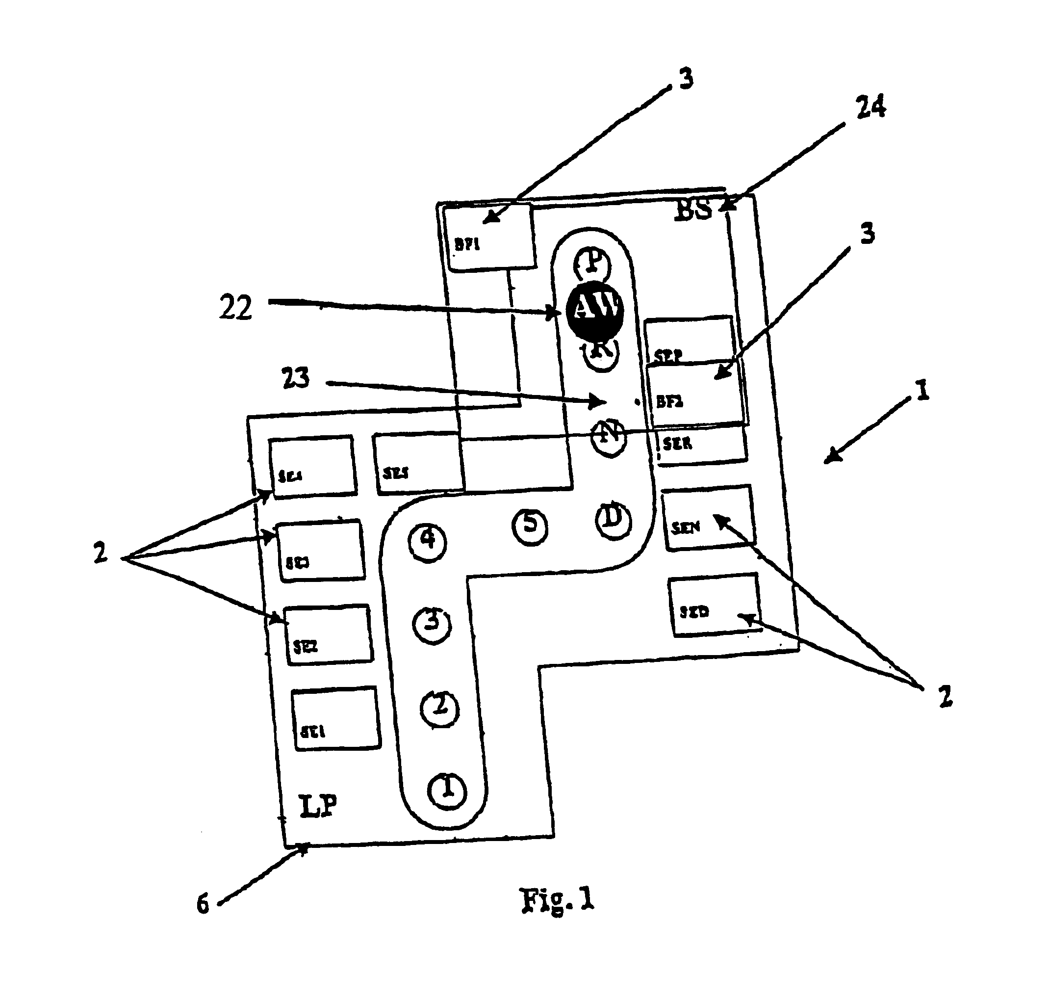
FIG. 2 shows a preferred embodiment of one of the inductive switching units 2. The inductive switching unit 2 i...


PUM


Abstract

A switching device, in particular a position sensing switching device, generates switching signals. The position sensing switching device comprises at least one switching unit and at least one activation unit, the switching unit reacting to a relative spacial displacement of the switching unit and the activation unit with respect to one another by outputting appropriate switching signals. The switching unit is embodied as an inductive switching unit and the activation unit is embodied as an inductive damping unit. The position sensing switching device according to the invention is preferably applied in gear-speed-changing units for automatic gearboxes.

Description

BACKGROUNDThe present invention relates to a switching device, in particular a position sensing switching device, which generates switching signals.Different switching devices are known from the prior art, most switching devices using mechanical switches. However, a significant disadvantage of these switching devices is that they have mechanical switching units or mechanical microswitches and mechanical sliding contacts for generating switching signals. The mechanical switches have the disadvantage that they do not operate without wear. Their service life is limited, on the one hand, by material erosion of contacts, by changes in material (oxidation) and by deposition on the switching contacts which are caused by mechanical friction, electrical overloading or the occurrence of an arc during the switching-off or switching-over process. The vibrations of the entire gate-type-gear changing unit also lead to increased wear of of the sliding contacts and sliding tracks of the mechanical ...

Claims


Application Information

Patent Timeline
Patent Type & Authority Patents(United States)
IPC IPC(8): H03K17/965H03K17/94H03K17/95B60K20/02G05G1/015
CPCF16H59/105H03K17/965H03K17/9525
Inventor ZAPF, MARTINKUGLER, ALEXANDERHAHN, GERHARD
Owner ZF FRIEDRICHSHAFEN AG
Why Eureka
Try Eureka