Mounting apparatus for data storage devices

a data storage device and mounting device technology, applied in the direction of electric apparatus casings/cabinets/drawers, washstands, instruments, etc., can solve the problems of time-consuming and cumbersome insertion and removal of screws, slide members have to be unscrewed, and screw insertion and removal is still time-consuming and cumbersom

Inactive Publication Date: 2005-02-08
HON HAI PRECISION IND CO LTD
View PDF11 Cites 83 Cited by
  • Summary
  • Abstract
  • Description
  • Claims
  • Application Information

AI Technical Summary

Benefits of technology

Accordingly, an object of the present invention is to provide a mounting apparatus which readily allows attachment and removal of a data storage device to and from a drive bracket.
To achieve the above-mentioned object, a mounting apparatus in accordance with a preferred embodiment of the present invention is adapted to mount a data storage device in a computer enclosure. The mounting apparatus includes a drive bracket, an operating body, a data storage device, and a pair of slide members. The drive bracket includes two opposite lateral walls. A first hole and a second hole are defined in one of the lateral walls. A stop plate is inwardly formed from said one of the lateral walls, rearwardly of the holes. The operating body is secured to said one of the lateral walls of the drive bracket. The operating body includes a first wedge formed on a resilient tongue, and a second wedge. The first and second wedges engage in the first and second holes of said one lateral wall of the drive bracket respectively. The slide members are attached to opposite sides of the data storage device, and the data storage device is slid into the drive bracket. One of the slide members corresponding to said one lateral wall includes a protrusion and an end buffer. The protrusion snappingly engages with the first wedge so that it abuts the first wedge and prevents said one of the slide members from moving back out from the drive bracket. The buffer abuts the stop plate of said one lateral wall and prevents said one of the slide members from moving too far into the drive bracket.

Problems solved by technology

A significant drawback of this means is that the insertion and removal of screws is time consuming and cumbersome, particularly due to workspace restrictions and accessibility limitations existing within a typical computer chassis.
Insertion and removal of the screws is still time consuming and cumbersome.
However, when the data storage device needs to be maintained or replaced, the slide members have to be unscrewed therefrom.
This operation is time consuming and cumbersome.

Method used


Image

  • Mounting apparatus for data storage devices
  • Mounting apparatus for data storage devices
  • Mounting apparatus for data storage devices

Examples


Embodiment Construction

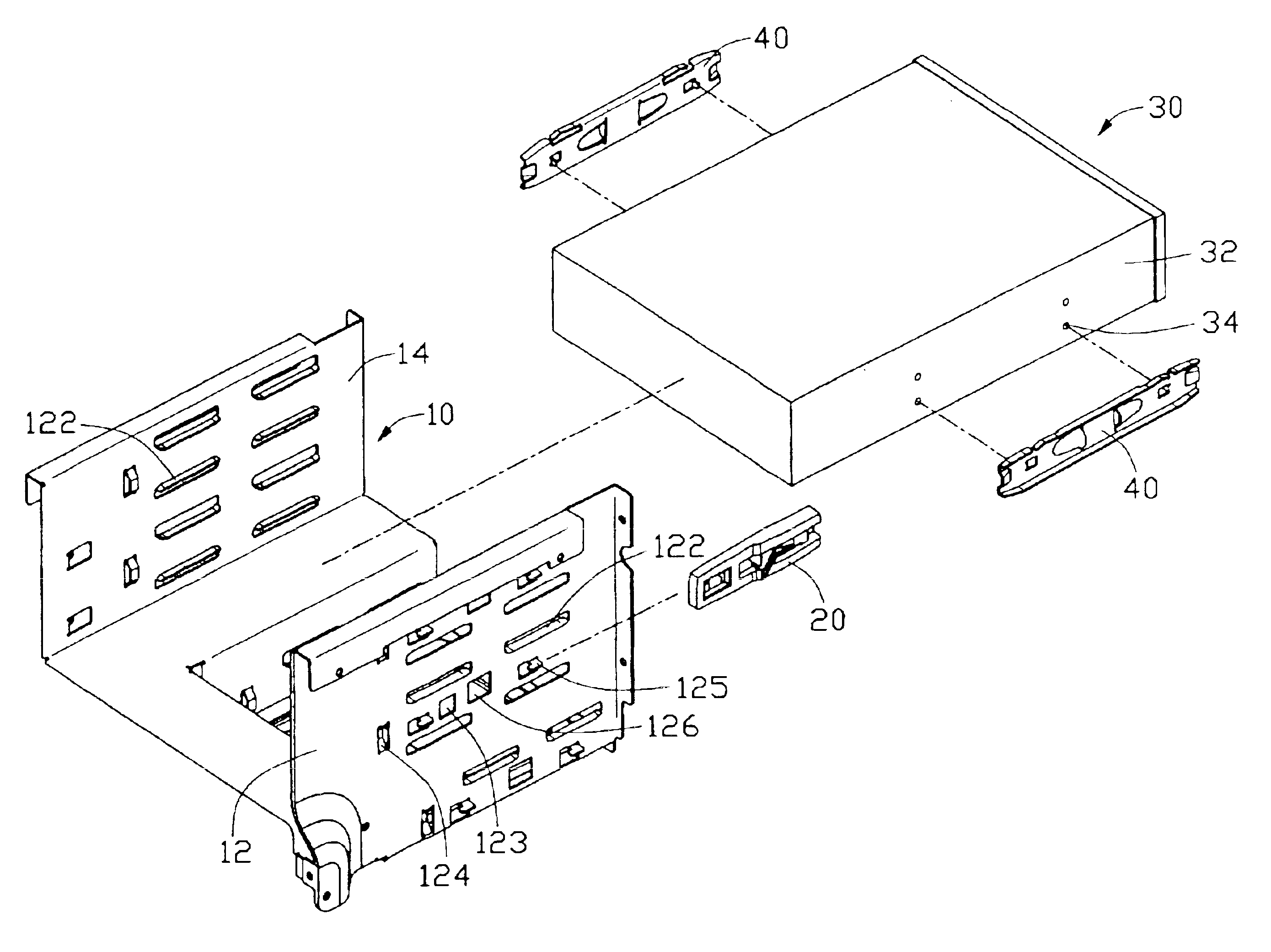
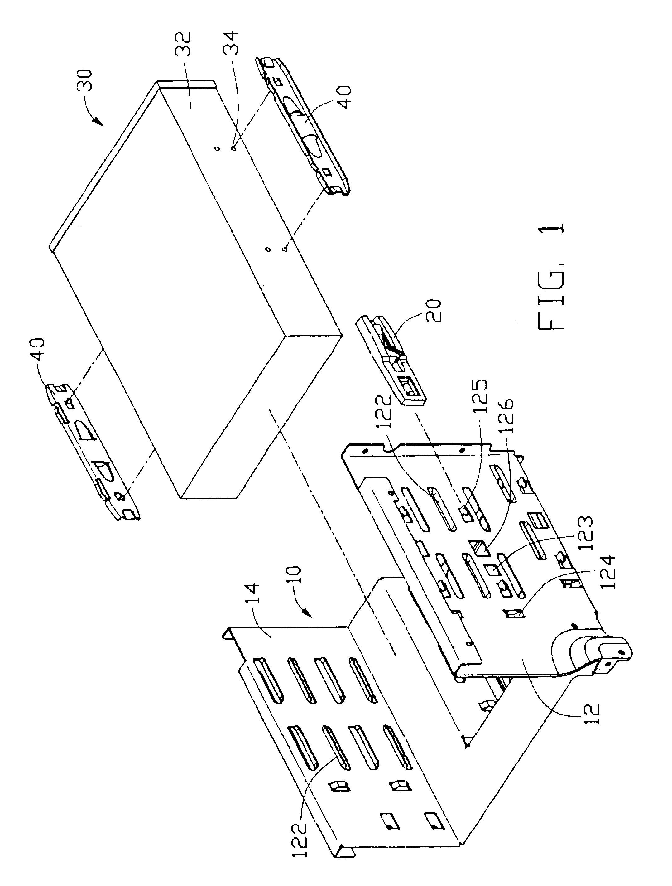
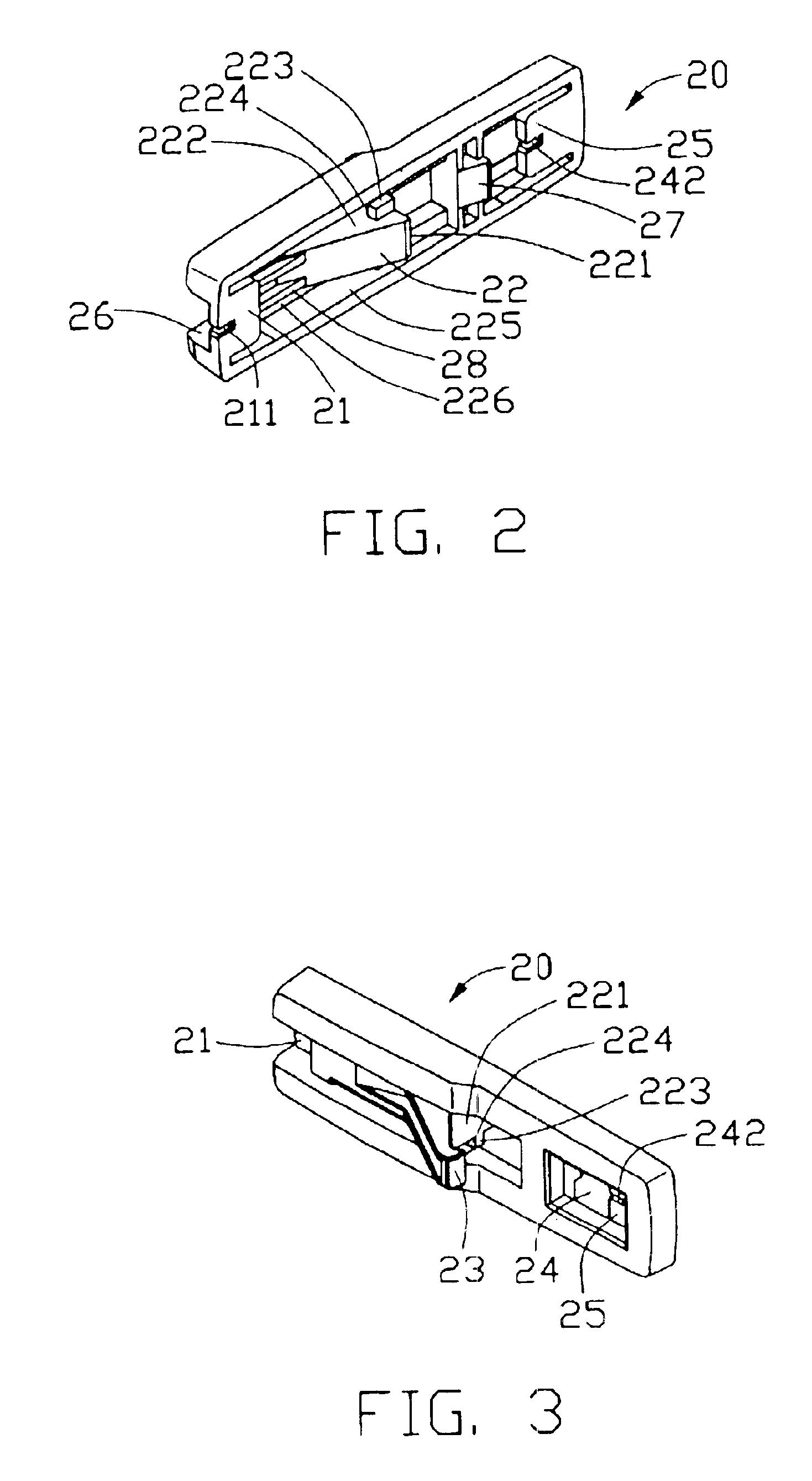
Referring to FIG. 1, a mounting apparatus for data storage devices in accordance with a preferred embodiment of the present invention comprises a drive bracket 10, an operating body 20, a data storage device 30 and a pair of slide members 40.

The data storage device 30 comprises two opposite side walls 32. A plurality of locking holes 34 is defined in each side wall 32.

The drive bracket 10 comprises two opposite upright lateral walls 12, 14. The lateral wall 12 defines a first hole 126 in a center thereof, and a second hole 123 rearwardly of the first hole 126. Two horizontal generally L-shaped hooks 125 are stamped outwardly from the lateral wall 12 at opposite sides of the first and second holes 126, 123 respectively, such that the hooks 125 and the first and second holes 126, 123 are horizontally aligned. A stop plate 124 is stamped inwardly from the lateral wall 12, rearwardly of the hooks 125. A pair of aligned support tabs 122 is stamped perpendicularly inwardly from the latera...


PUM


Abstract

A mounting apparatus includes a computer drive bracket (10), an operating body (20) attached to a lateral wall (12) of the drive bracket, a data storage device (30), and two slide members (40) attached to sides of the storage device. First and second holes (126, 123) are defined in the wall, and a stop plate (124) is formed from the wall. The operating body includes: a resilient tongue (28) having a first wedge (22); and a second wedge (27). The first and second wedges engage in the first and second holes respectively. One slide member includes a protrusion (49′) and a buffer (47′). The protrusion snappingly engages with the first wedge so that it abuts the first wedge and prevents said slide member from moving back out from the drive bracket. The buffer abuts the stop plate and prevents the slide member from moving too far into the drive bracket.

Description

BACKGROUND OF THE INVENTION1. Field of the InventionThe present invention relates generally to apparatuses for mounting computer components within a computer enclosure, and more particularly to a mounting apparatus for easily installing and removing data storage devices such as disk drives.2. Related ArtA number of different means and devices are used to mount data storage devices, such as disk drives or CD-ROMs, to drive brackets of computer enclosures. One widely used conventional means is to simply screw the data storage device directly to a drive bracket. A significant drawback of this means is that the insertion and removal of screws is time consuming and cumbersome, particularly due to workspace restrictions and accessibility limitations existing within a typical computer chassis. More recent developments facilitate installation and removal of data storage devices by other means. These include the use of guide rail type devices, such as those described below.Taiwan Patent Publ...

Claims


Application Information

Patent Timeline
Patent Type & Authority Patents(United States)
IPC IPC(8): G06F1/18
CPCG06F1/187G06F1/184
Inventor XU, JI-GUO
Owner HON HAI PRECISION IND CO LTD
Why Eureka
Try Eureka