Optical fiber drop cable

a drop cable and optical fiber technology, applied in the field of optical fiber drop cables, can solve problems such as danger and unpreferability

Inactive Publication Date: 2005-02-08
THE FUJIKURA CABLE WORKS LTD
View PDF8 Cites 5 Cited by
  • Summary
  • Abstract
  • Description
  • Claims
  • Application Information

AI Technical Summary

Problems solved by technology

However, since the tension members T of the optical element portion 102 are conductive metal wires, a portion thereof led inside the house is exposed to danger of a thunderbolt accident, which is dangerous and unpreferable.

Method used


Image

  • Optical fiber drop cable
  • Optical fiber drop cable
  • Optical fiber drop cable

Examples


first embodiment

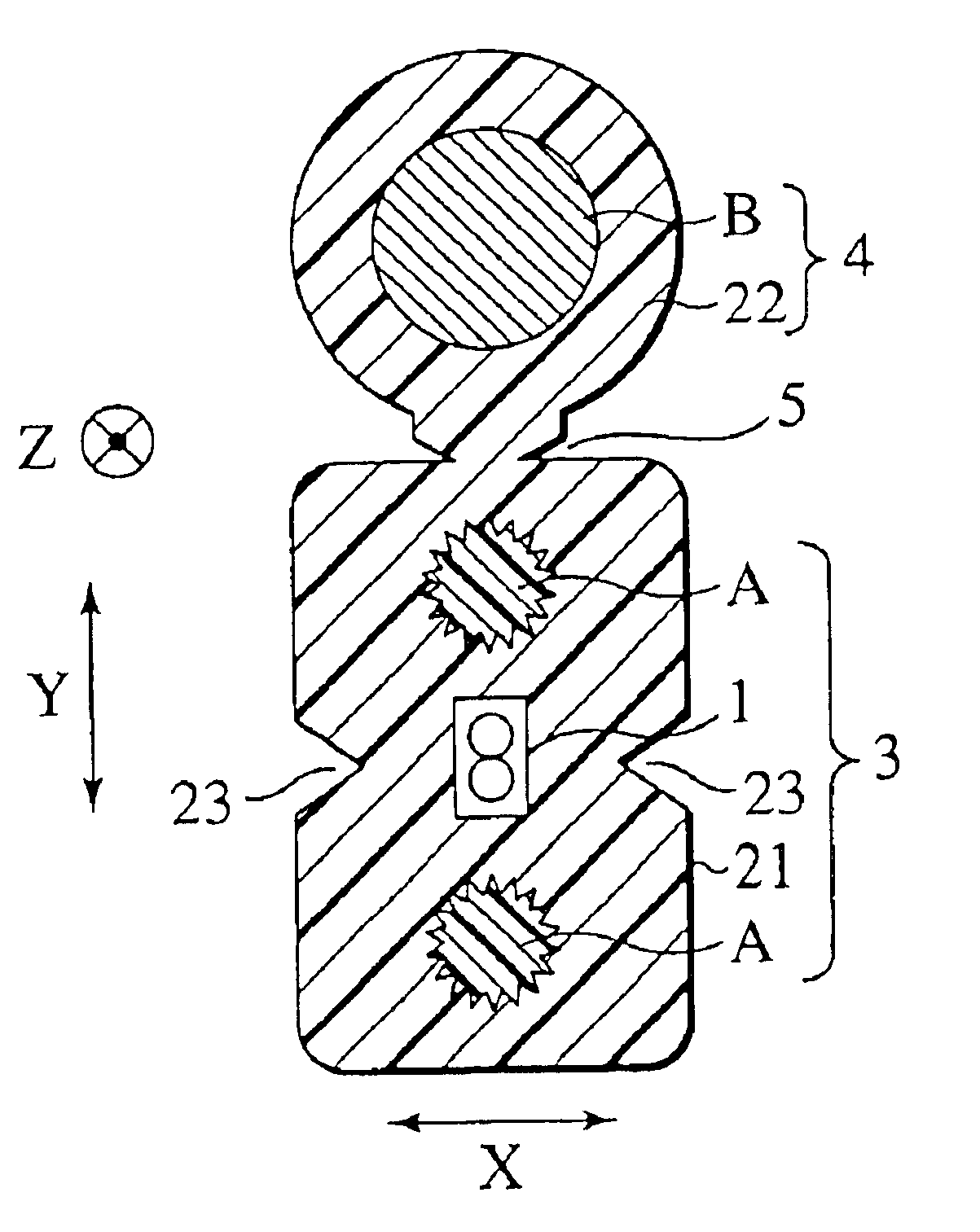
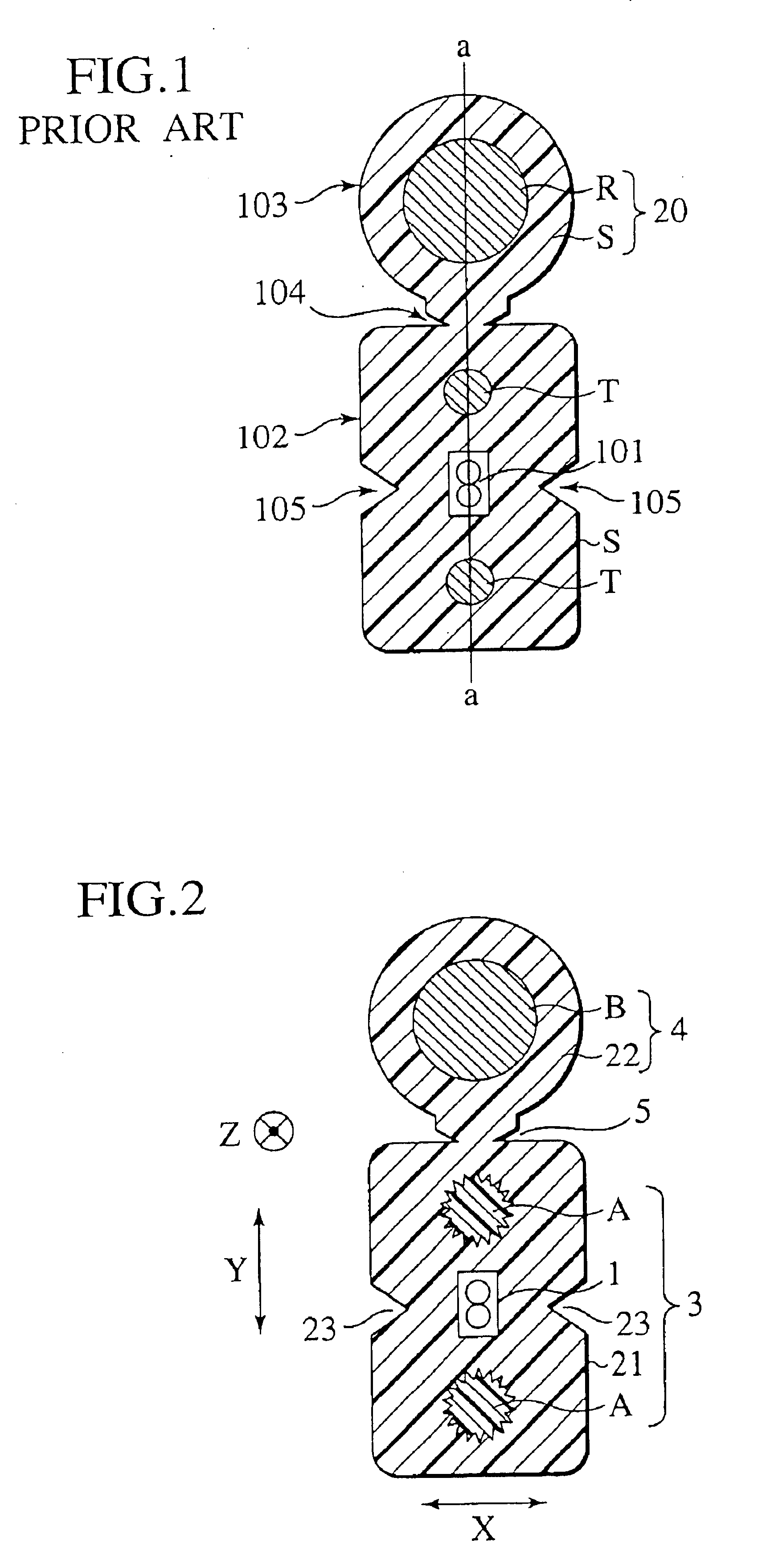
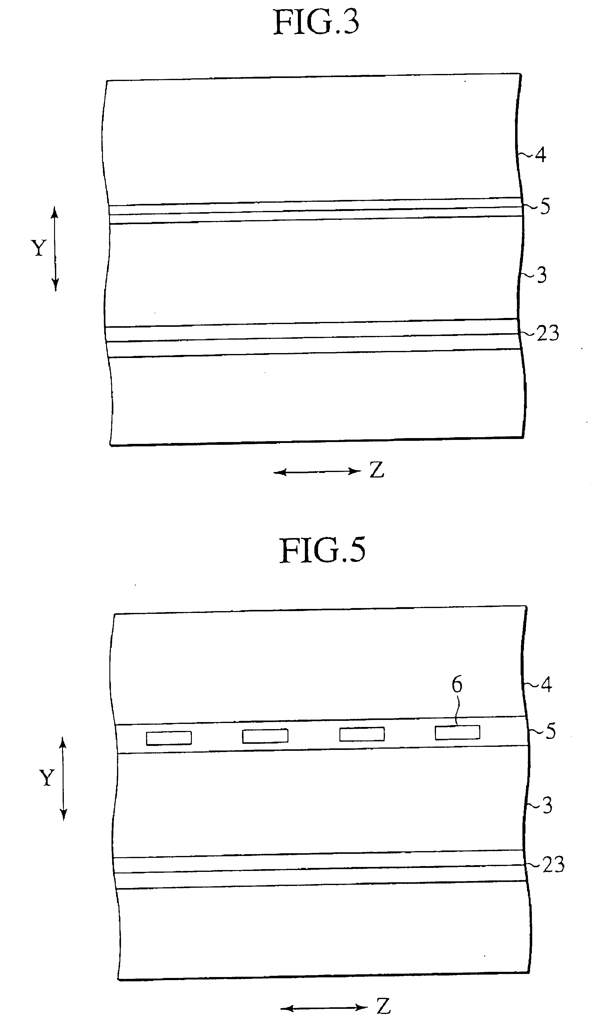
Description will be made in detail for an embodiment with reference to FIGS. 2 to 4. When an optical fiber is dropped from an optical fiber cable hung in the air into a home, as will be described later, an optical element portion of an optical fiber drop cable is separated from a cable support wire portion, and the optical fiber is led into a subscriber's house. Accordingly, in order to prevent the subscriber's house from being struck by a thunderbolt or affected thereby, it is necessary to constitute the optical element portion entirely of a nonconductive material. Furthermore, a tensile strength property of the optical element portion must be realized in a similar extent or more to the case of using a steel wire for a tension member.

According to this embodiment, at least a pair of first tension members A, which are nonconductive and long-scale, are disposed parallel to the cable (in a Z direction) on both sides of an optical fiber single core wire or optical fiber tape core wire 1...

second embodiment

Description will be made for a second embodiment of the present invention with reference to the drawings. With reference to FIG. 6, an optical fiber drop cable 301 according to this embodiment is constituted of a long-scale optical element portion 3 having an optical fiber single core wire or an optical fiber tape core wire (hereinafter, these are generically referred to as an optical fiber core wire 1) buried in a sheath 21 and a long-scale cable support wire portion 4 composed by being monolithically fixed parallel to this optical element portion 3 continuously or intermittingly with a constricted neck portion 9 interposed therebetween.

In the optical element portion 3, at least a pair of long-scale tension members A′ as first tension members are disposed parallel to the optical fiber core wire 1 on both sides thereof in a sandwiching manner. These elements are coated with the cable sheath 21 formed of a thermoplastic resin such as polyethylene and polyvinyl chloride (PVC), and thu...


PUM


Abstract

An optical fiber drop cable includes an optical element portion having an optical fiber core wire and a pair of first tension members disposed parallel to the optical fiber core wire on both sides thereof in a sandwiching manner. The optical fiber core wire and the pair of first tension members are coated with a cable sheath. A long-scale cable support wire portion has a second tension member coated with a sheath. The optical element portion and the cable support wire portion are adhered parallel to each other. The first tension members are composed of a nonconductive material. A flexural rigidity of the optical element portion is in a range from 80 to 500 Nmm2.

Description

BACKGROUND OF THE INVENTIONIn order to realize the FTTH (Fiber to the Home), that is, to make it possible to transmit / receive high-speed and wide-range information such as ultra high speed data to / from a home and an office, an optical fiber drop cable has been used, which is suitable for dropping a core wire of an optical fiber cable extended from a telephone station to a subscriber's house such as a general house and wiring this core wire there. Specifically, the optical fiber drop cable (outside wire) is a cable for use when the optical fiber is led from an electric pole into the home.As shown in FIG. 1, an optical fiber drop cable including an optical fiber core wire or optical fiber tape core wire 101 and a pair of conductive metal wires on both sides thereof has been known. Such an optical fiber drop cable includes an optical element portion 102 having the optical fiber core wire and tension members T composed of, for example, steel wires added thereto, both of which are coated...

Claims


Application Information

Patent Timeline
Patent Type & Authority Patents(United States)
IPC IPC(8): G02B6/44
CPCG02B6/4429G02B6/4403
Inventor KOBAYASHI, KAZUNAGAKUSAKARI, MASAHIROMIYAMOTO, MATSUHIROWATANABE, HIROHITOOHASHI, KEIJI
Owner THE FUJIKURA CABLE WORKS LTD
Why Eureka
Try Eureka