Semi-cordless unbalanced spring driven blind system and methods for adjusting and making same

Inactive Publication Date: 2005-02-15
ROLLERASE INC
View PDF18 Cites 45 Cited by
  • Summary
  • Abstract
  • Description
  • Claims
  • Application Information

AI Technical Summary

Benefits of technology

is to provide a blind that can be operate

Problems solved by technology

However, these cord-type interfaces typically hang freely in a loop or as two separated lengths of cord.
Recently, consum

Method used


Image

  • Semi-cordless unbalanced spring driven blind system and methods for adjusting and making same
  • Semi-cordless unbalanced spring driven blind system and methods for adjusting and making same
  • Semi-cordless unbalanced spring driven blind system and methods for adjusting and making same

Examples


Embodiment Construction

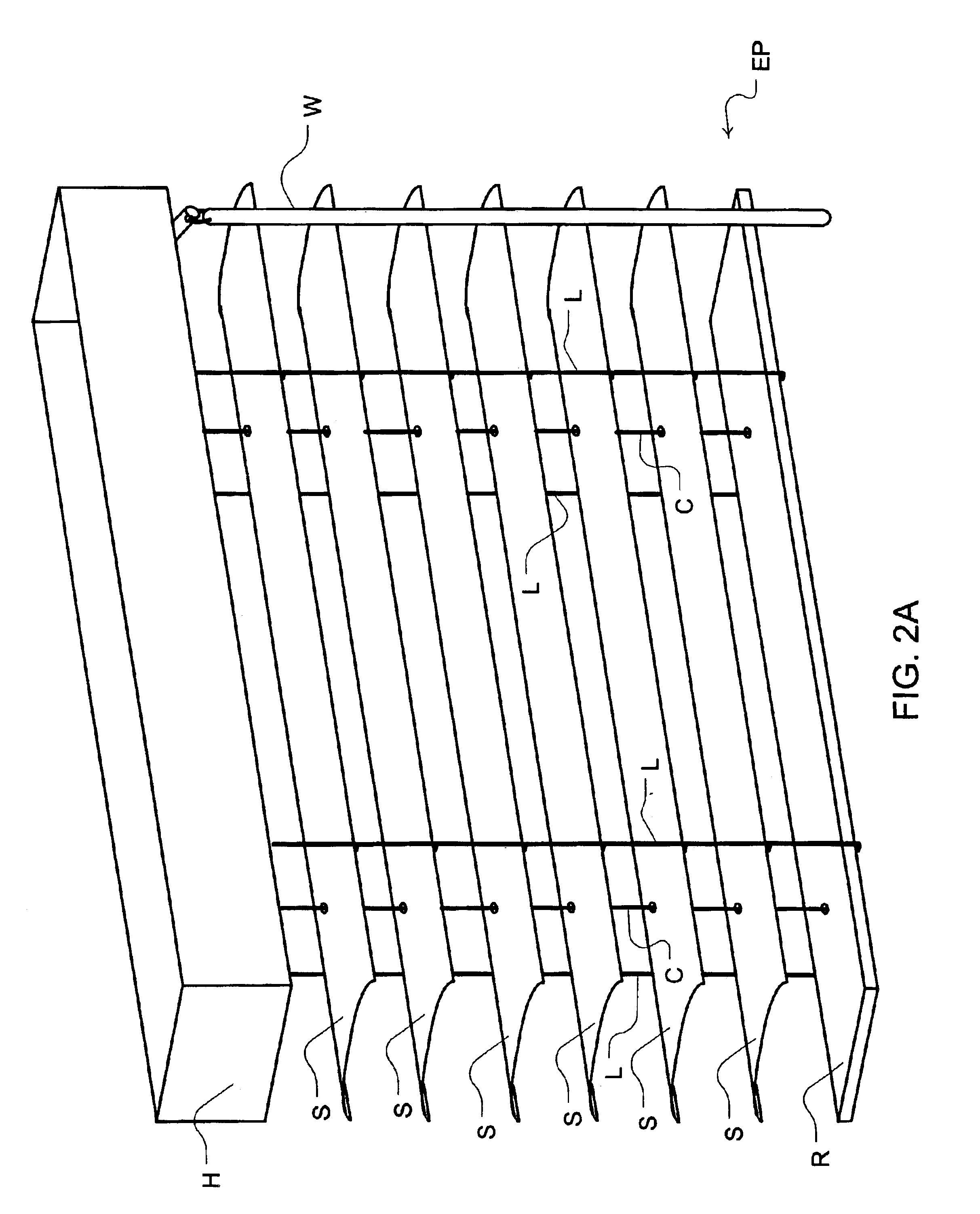
As illustrated in FIGS. 2A and 2B, a horizontal blind B includes a head rail H and slats S. The blind B also utilizes lift material such as lift cord C or ladder material such as a ladder cord L which are integrated with the slats S. The lift cords C permit the slats S to be raised and lowered relative to the head rail H. The ladder cords C provide support for the slats S when the slats S are extended down from the head rail H. The ladder cords C also permit the slats S to be tilted if the front portion of the ladder cord C is raised as the back portion of the ladder cord C is lowered or vice versa. The lifting and tilting of these cords is controlled by the apparatus within the head rail H. Depending on the control apparatus provided, a user interface, shown as a flexible wand W in FIGS. 2A and 2B, may be used to tilt the slats S by twisting the wand W, and / or release the slats S for raising or lowering by pulling the wand. Although the wand W is a preferred user interface, those s...


PUM


Abstract

The invention includes an unbalanced horizontal blind with a spring means to provide a lifting or retraction force for the slats of the blinds. A brake means prevents undesired movement of the slats that would otherwise result from the continuous retraction force of the spring means when the slats are set in a desired position. Controls for the release of the brake means and tilting are also provided in an embodiment of a blind of the invention. An embodiment of the invention permits the blind to be operated by a single wand that can be used to either raise the slats or tilt the slats. This eliminates the need for a loose cord or bead chain that would traditionally be used as the user interface for controlling the movement of the slats of the blind.

Description

FIELD OF THE INVENTIONThe invention relates to the field of window treatments. More specifically, the invention is a system for controlling the lift or lift and tilt of an unbalanced window treatment in the presence of a continuous retraction force.BACKGROUND OF THE INVENTIONIn the construction of horizontal blinds two kinds of controls are usually desired. The blind can have a control to lift the slats of the blind. In addition, the blind may permit control over the tilt of the slats. Cords or tape will generally be attached to or through the slats of the blind and into the head rail of the blind to connect with the control apparatus. To allow a user to operate the blind, an external interface is provided. Traditionally, the interface for lifting includes a cord extending from the head rail of the blind. When separate controls are provided for lift and tilt, typically a wand is utilized to change the tilt of the slats. Depending on the control devices used in the head rail, a cord ...

Claims


Application Information

Patent Timeline
IPC IPC(8): E06B9/30E06B9/28E06B9/38E06BE06B9/322E06B9/62
CPCE06B9/322E06B9/62
Inventor CROSS, DAVIDZAKOWSKI, JOSEPH W.BALTA, MARTINATHITANG, AMNOUYCHURCHILL, JR., RAYMOND B.
Owner ROLLERASE INC
Why Eureka
Try Eureka