
Aircraft kite

a technology for aircraft and wings, applied in the field of aircraft kits, can solve the problems of affecting the shape of the wing, and the physical appearance so as to improve the stability and performance of the aircraft kite, reduce the fluttering of the wing, and effect the flight characteristics of the wing

Inactive Publication Date: 2005-02-15
TABOR DON
View PDF66 Cites 14 Cited by
  • Summary
  • Abstract
  • Description
  • Claims
  • Application Information

AI Technical Summary

Benefits of technology

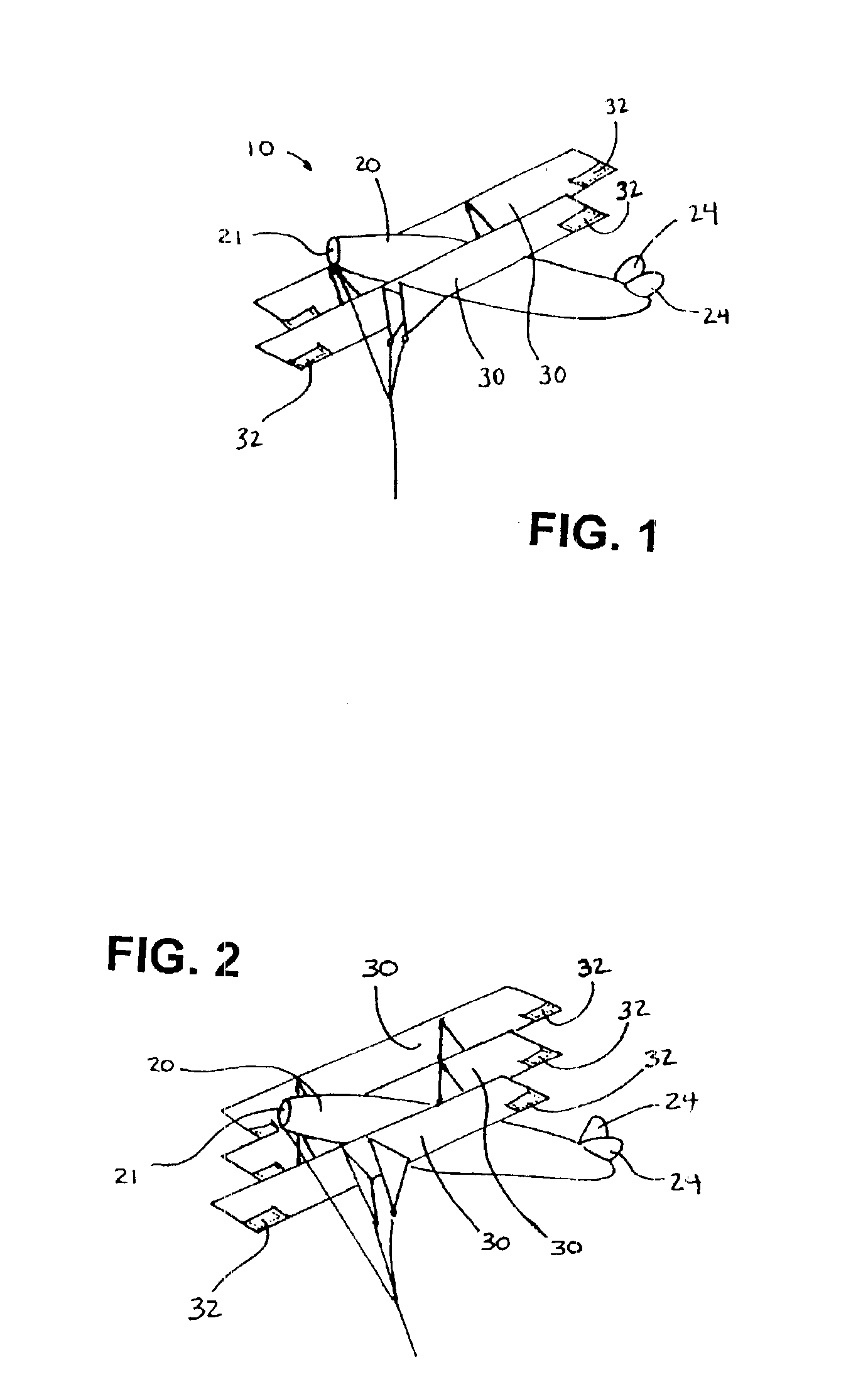
Additionally, in one embodiment, the shape of each wing is maintained in flight with a minimum of struts and spars by using one or more scoops or pockets fixed to the lift surfaces of the wings. During flight, the pockets catch air and thereby reduce fluttering of the wing and force the trailing edge of the wing back. Moreover, the pockets thereby effect the flight characteristics of the wing and greatly improve the stability and performance of the aircraft kite. As a result, the aircraft kite of the present invention has improved stability and performance with respect to earlier aircraft kite designs, and it utilizes less rigid parts making the kite easier to assemble, more convenient to store and ship, and less vulnerable to breakage in transit and during operation.
Stability and performance are further improved by using inflatable tail fin members. As with the wing pockets, the tail fin members catch air during flight through openings at or near the point where the tail fin member is connected to the fuselage portion of the kite. Whether the tail fin members catch air from within the fuselage (as a closed windsock) or from outside the fuselage, the tail fin members greatly add to the stability and flight characteristics of the kite and effect the angle of attack like a real airplane. The stability and performance characteristics are further improved by the use of twin keels connecting the kite to the kite string, providing a 3-point twin keel kite string harness connection.
One objective of this invention is to make an airplane kite having improved stability and performance, and reduce or eliminate independent wing oscillation, by using air scoop pockets in its one or more wings and alternatively in its tail fins. Stability and performance are also improved by utilizing one or more ram air openings for receiving air during flight in an otherwise closed airfoil-shaped fuselage. Another objective of this invention is to make an airplane kite that has a realistic appearance in flight, including having one or more wings that are rectangular. Yet another objective of this invention is to make an airplane kite that can be easily and efficiently manufactured employing relatively few parts, and thereby also easily assembled by even novice operators, disassembled, stored and transported. Another objective is to minimize the number of parts and thereby minimize the exposure to breakage during operation, transport, and storage.
Yet another objective of this invention is to make an airplane kite that may be assembled to have any number of wings still maintaining the ease of assemble and a minimum of manufacturing costs.

Problems solved by technology

However, there are substantial disadvantages to making aircraft kites that physically look like a true vintage Sopwith Camel and Fokker-era single winged, bi-winged, or tri-winged airplanes, with their rectangular-shaped wings.
These approaches are unsatisfactory because of the excessive number of parts required for assembly and the resulting difficulty of assembly.
Since both the leading edge and outer edge are reinforced using a spar, the wing cannot be rolled up when being stored or shipped.
Thus, once assembled, such a kite, with its numerous rigid struts and spars, would be vulnerable to being damaged during shipment, on the sale room floor, or when it is transported to the desired flight location.
This is also unsatisfactory since the aforementioned vintage planes had rectangular wings.
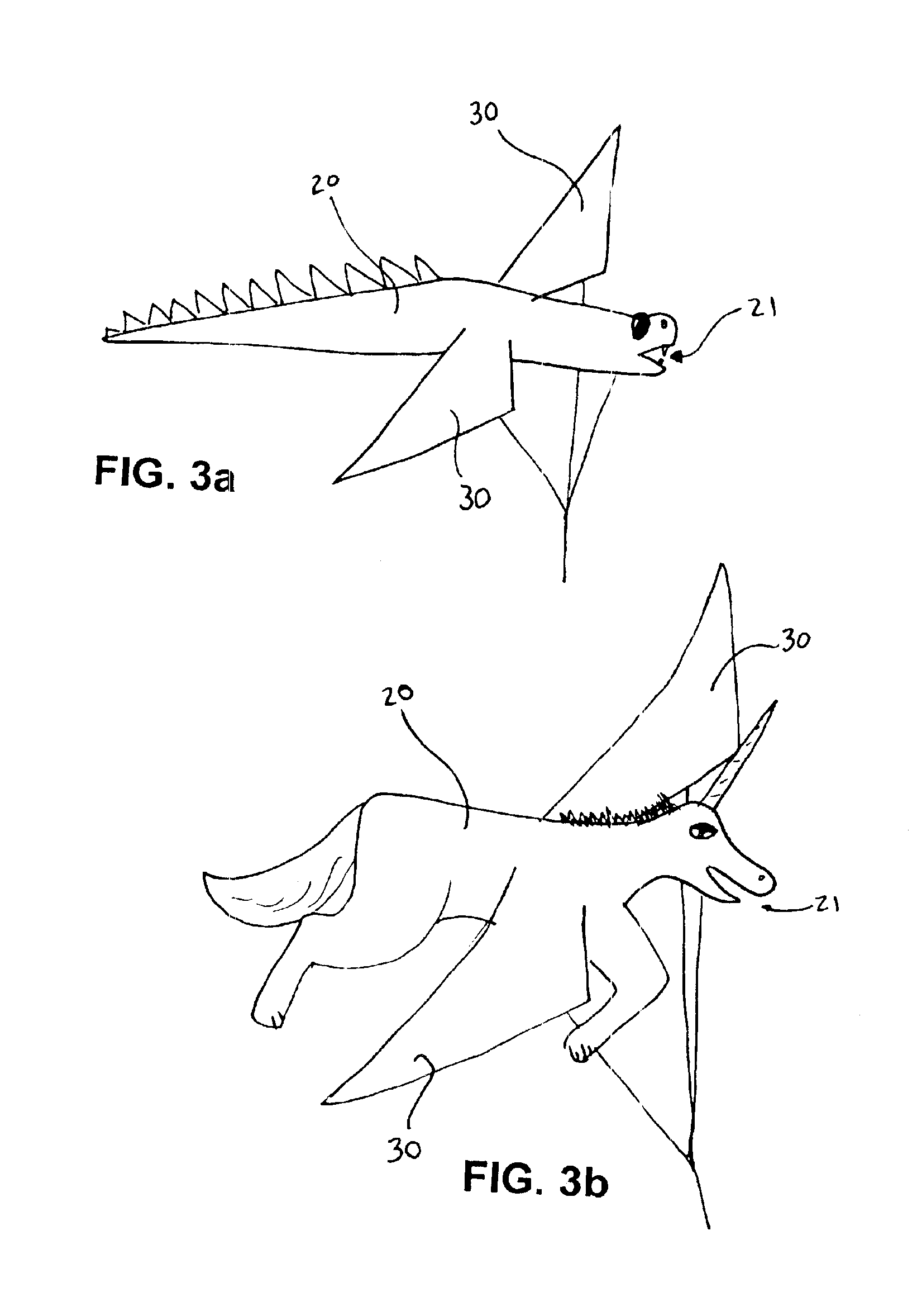
Similarly, other aircraft kites such as fanciful space craft and animal kites have suffered from the need for an excessive number of rods, struts, and spars to maintain the unique shape during flight.
Additionally, the aforementioned aircraft kites generally have a degree of instability that is unpleasant and discouraging to novice and veteran kite fliers alike.
Also, most or all mono-winged, bi-winged, and tri-winged aircraft kites are limited to their particular configuration.

Method used


Image

  • Aircraft kite
  • Aircraft kite
  • Aircraft kite

Examples


Embodiment Construction

)

The detailed description set forth below in connection with the appended drawings is intended as a description of presently-preferred embodiments of the invention and is not intended to represent the only forms in which the present invention may be constructed and / or utilized. References to an airplane form is meant as illustrative of a preferred embodiment and for convenience of example. Airplane as used herein has been specifically defined above.

For the sake of convenience and clarity, this disclosure makes references throughout to kites having “airplane” forms, and “airplane” is defined for the purposes of this application to mean any aircraft, real or fictional, man-made or natural. Where wings are unnecessary to explain the present invention, the definition includes any such aircraft, whether or not it has wings, such as dirigibles, spacecraft without wings, wingless animals, and the like. The following describes one preferred embodiment, namely an aircraft or airplane kite ha...


PUM


Abstract

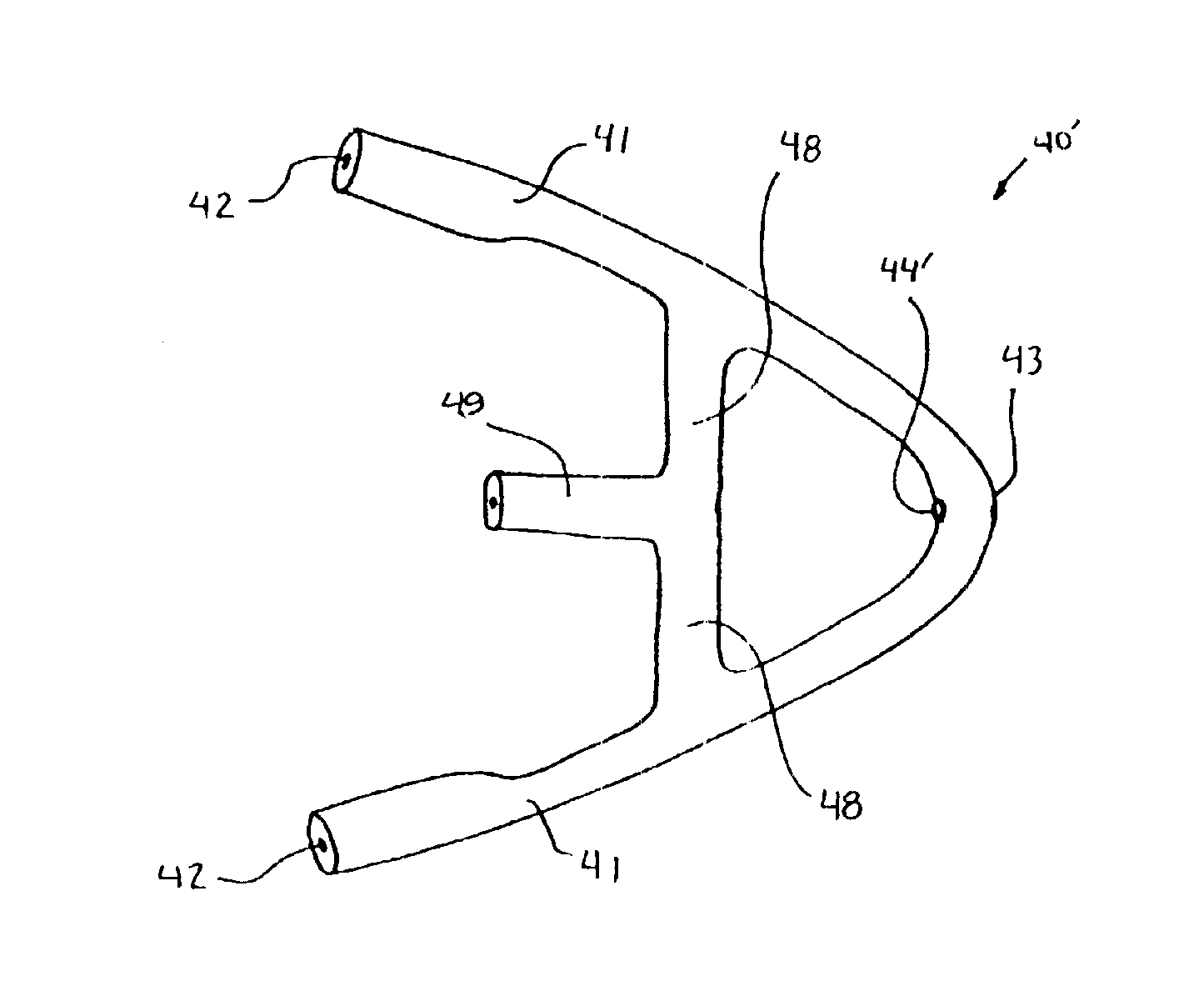
A kite in the shape of an aircraft having one or more wings. The number of wings can vary due to novel V-shaped connection members employed together with strut rod members cut to predetermined lengths. The connection members are preformed V-shaped connectors slidably mounted to spar members disposed in open-ended sleeves in the leading and trailing edges of a wing and may be oriented to receive strut members form either above or below the wing, for efficiency manufacturing, ease in assembly, and minimum exposure to breakage during operation, storage and transport. Additional connection members may be added to the spar members to receive strut members connected to additional wings thereby allowing for an airplane kite having one wing, two wings, three wings, or more. Multiple-V connectors may be combined to create hubs for propellers or wheels that rotate when they encounter a front wind. Ram air openings are utilized in the fuselage of the kite to maintain the shape of the fuselage and the angles of wings. Additionally, the wings are equipped with air scoop pockets for added stability and performance under a large spectrum of flying conditions and improved appearance of the wings without requiring spars along the out edges of the wings. Similar ram air openings or air scoop pockets are utilized in the tail fin members for increased stability and flight characteristics, the tail fins receiving air from either within the fuselage or from outside the fuselage, respectively.

Description

BACKGROUND OF THE INVENTIONThis invention relates to a kite in the shape of an aircraft, such as an airplane, and more particularly, aircraft kites in which assembly is made simple, storage and shipping is made simple, and flying is made simple.Aircraft kites such as kites in the shape of airplanes, space craft, and fanciful flying animals have been made by others. However, there are substantial disadvantages to making aircraft kites that physically look like a true vintage Sopwith Camel and Fokker-era single winged, bi-winged, or tri-winged airplanes, with their rectangular-shaped wings. In order to maintain the wings' shape in flight, previous approaches included lining both the leading and outer edges of the wing with spars made of rigid material such as wooden, plastic or metal rods or tubes. Another approach included extensive use of struts and braces.These approaches are unsatisfactory because of the excessive number of parts required for assembly and the resulting difficulty ...

Claims


Application Information

Patent Timeline
IPC IPC(8): A63H27/08A63H27/00
CPCA63H27/08
Inventor TABOR, DON
Owner TABOR DON
Learn More