Zero ground disturbance system

a ground disturbance and zero-level technology, applied in the field dike apparatus, can solve the problems of entrapped hazardous materials that are often left indelible on the surrounding surface, unable to meet the needs of storage tank spillage, so as to achieve the effect of reducing the risk of leaking

Active Publication Date: 2005-02-15
GLOBALFOUNDRIES US INC +1
View PDF9 Cites 34 Cited by
  • Summary
  • Abstract
  • Description
  • Claims
  • Application Information

AI Technical Summary

Benefits of technology

In the illustrated embodiment, the base plate is positioned so that a substantial portion of the proximate end extends within the region defined by the inner chamber, as illustrated in FIGS. 3, 4, 7, 8, and 9. This configuration allows the base plate to use the weight of both the released materials from the primary storage vessel and the components of the containment system that are located above that portion of the base plate that is within the inner chamber to resist the bending moment created at the base of the dike apparatus, thereby preventing the base plate and attached brace and walls from tipping over in a generally outwardly direction.
The side extensions are configured to provide traction for the base plate. When subjected to the weight of said released materials and the dike apparatus, the lower portion of the side extensions aid in gripping the surrounding ground so as to resist any lateral movement caused by the outwardly forces that are exerted by the spilled or leaked material against the walls of the dike apparatus.
The illustrated embodiment of the present invention also preferably includes at least one base support channel that is operably connected to the base plate. The base support channel is configured to provide additional stiffness to the base plate so as to provide additional resistance against any bending moment that may be created at the base of the dike apparatus. In an attempt to not compromise the stability of the brace assembly, the base support channel is preferably recessed into the base plate, whereby the base support channel attaches to the bottom surface of the base plate and does not extend beyond the lower portion of the side extensions or the proximate or distal ends of said base plate. Alternatively, the base plate channel may be constructed to provide sufficient stiffniess so as to eliminate the need for a brace support channel.
To further prevent the lateral movement of the walls when the walls of the dike apparatus are subjected to the outwardly forces created by the release of material from primary storage vessel, the dike apparatus of the present invention also preferably includes at least one support cable. The support cable preferably has a first end and a second end, the first end being secured to a first brace assembly and the second end being secured to a second brace assembly, the first and second brace assemblies preferably being located across from one another on opposing walls. When secured to the brace assemblies, the support cable extending across the inner chamber is preferably maintained in a taut condition so as to assist in resisting any outwardly forces that may be exerted against said walls and the brace assemblies.

Problems solved by technology

However, storage tanks have been known to occasionally accidentally leak or spill the entrapped hazardous material.
However, the construction of dike apparatuses from such materials, and their intended permanency, typically makes any attempt to subsequently expand these apparatus both labor intensive and expensive.
Furthermore, when removed or vacated, such apparatuses often leave an indelible mark on the surrounding surface.
However, the metallic surfaces of these systems often prevent such dikes from being used in conjunction with the storage of materials that are highly reactive to metals, such as liquid fertilizers.
Furthermore, the reliance on support posts that are secured-beneath the surrounding ground subjects these systems to damage related to frost heavage.
Differential frost heavage typically results in the displacement of the support posts, and their attached wall sections, thus pulling the wall sections away from one another, and thereby potentially compromising the dike's seal of containment.
The need to fix this reoccurring separation between the wall sections so as to maintain the integrity of the dike apparatus typically makes these systems costly to maintain.
Drilling to such depths can be both expensive and labor intensive, particularly in light of the fact that site conditions throughout the world vary greatly.
For instance, in some areas, the presence of limestone or other rock strata makes drilling postholes very difficult and expensive.
In other areas of the world, or during winter months, frozen ground increases the difficultly and expense of installation.
Drilling to depths of up to eight feet also creates additional potential hazards, including the dangers associated with the drill hitting underground gas lines, electrical lines, and / or pipes.
Additionally, because such storage facilities are often located in remote areas, transporting cement to set the support posts in the postholes, as required by the '142 patent, is expensive.

Method used


Image

  • Zero ground disturbance system
  • Zero ground disturbance system
  • Zero ground disturbance system

Examples


Embodiment Construction

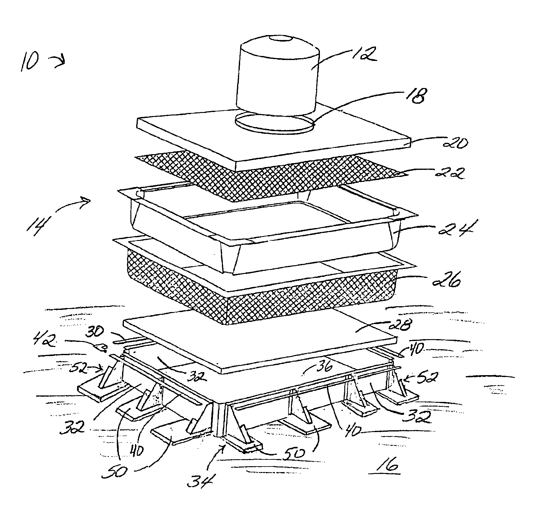
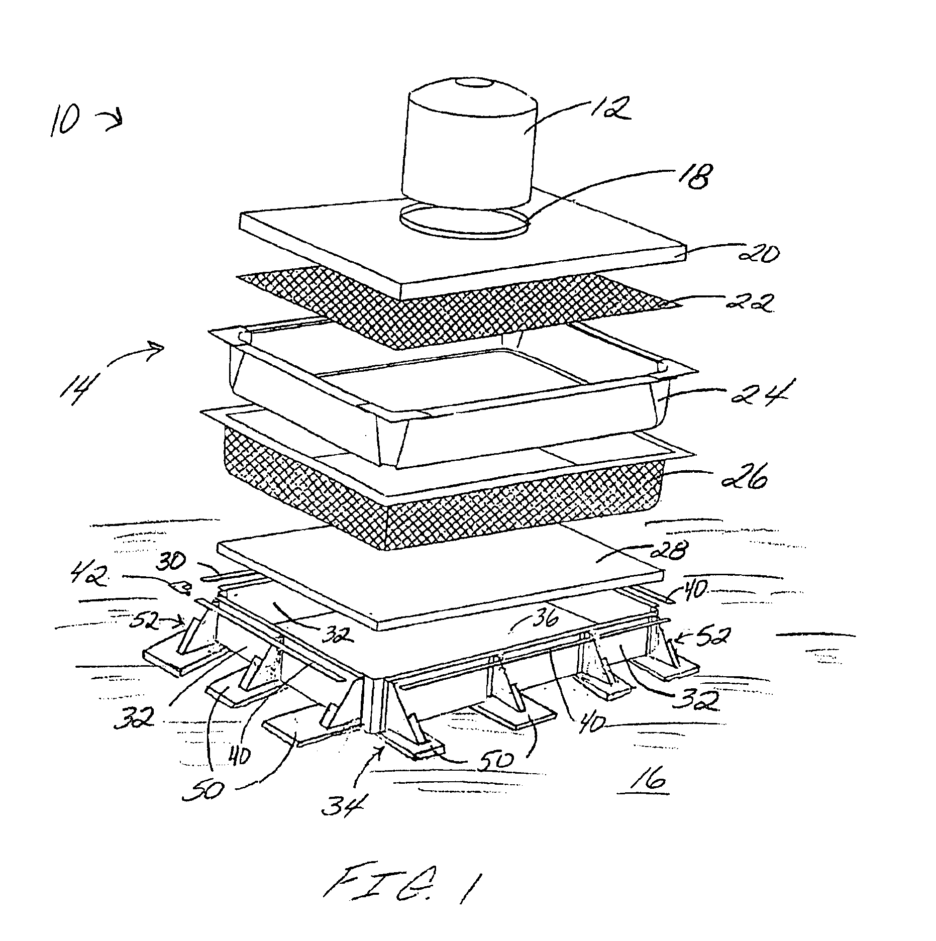
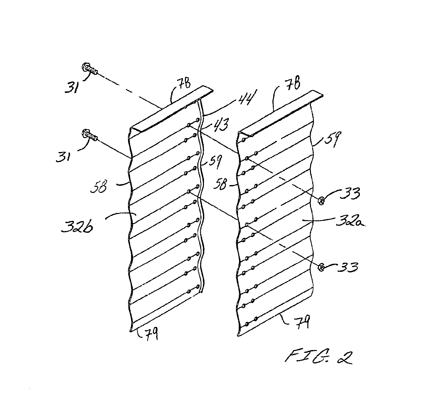
FIG. 1 illustrates a containment system 10 in accordance with the illustrated embodiment of the present invention. The containment system 10 is comprised of a primary storage vessel 12, such as a storage tank, that is configured to hold hazardous materials, and a secondary containment system in the form of a dike apparatus 14. The dike apparatus 14 is comprised of a plurality of brace assemblies 34 set upon the ground 16. The plurality of brace assemblies 34 provide support to a plurality of wall sections 32, at least a portion of the plurality of wall sections 32 preferably being bolted to at least a portion of an adjacent brace assembly 34. The wall sections 32 and attached brace assemblies 34 are arranged to create an enclosed inner chamber 36, as illustrated in FIGS. 1, 8, and 9. The region encapsulated within the inner chamber 36 extends down to at least the enclosed ground 16. The plurality of brace assemblies 34 are also preferably positioned along the plurality of wall secti...


PUM


Abstract

A zero ground disturbance dike apparatus and method for the secondary containment of harmful chemicals that are stored in primary storage vessels, wherein the dike apparatus does not require the drilling of postholes or the setting of support posts in concrete. Sections of dike walls are attached to bracing assemblies, each bracing assembly being comprised of a brace and a base plate. Braces are configured to support the assembled wall sections and to provide resistance against the outwardly force exerted by material that is released from the primary storage vessel. Base plates attached to the braces assist in resisting bending moments that may be created about the base of the dike apparatus. The brace assembly also preferably includes at least one base support channel for additional base plate stiffness and support cables to further resist the outwardly forces exerted against the dike apparatus by said released materials.

Description

BACKGROUND OF THE INVENTIONThe present invention pertains to the secondary containment of stored chemicals that are harmful to both the environment and living creatures. More particularly, the present invention relates to a zero ground disturbance dike apparatus for the secondary containment of stored harmful materials that does not require the drilling of postholes or the setting of support posts in concrete.The storage of hazardous materials, such as petroleum contaminated process-water, industrial chemicals, liquid agricultural chemicals, and other corrosive chemicals in storage tanks are well known. Such tanks are designed and fabricated to prevent the uncontrolled release of these and other hazardous materials into the environment so as to reduce the risks associated with the pollution of the surrounding area and / or potential contamination of nearby ground water.However, storage tanks have been known to occasionally accidentally leak or spill the entrapped hazardous material. I...

Claims


Application Information

Patent Timeline
Patent Type & Authority Patents(United States)
IPC IPC(8): B65D90/22B65D90/24
CPCB65D90/24
Inventor SIGLIN, DONALD J.VER STEEG, DAVID A.HAMMOND, CHARLES L.SEEBA, GARY D.POLZIN, KEITH M.HOOVER, GARY L.
Owner GLOBALFOUNDRIES US INC
Why Eureka
Try Eureka