
Precast concrete culvert system

a culvert system and concrete technology, applied in the direction of artificial islands, sewer pipelines, transportation and packaging, etc., can solve the problems of weight, height and length of each one-piece culvert unit, and achieve the effect of increasing the capacity of side wall sections

Inactive Publication Date: 2005-02-15
CONTECH ENGINEERED SOLUTIONS
View PDF17 Cites 30 Cited by
  • Summary
  • Abstract
  • Description
  • Claims
  • Application Information

AI Technical Summary

Benefits of technology

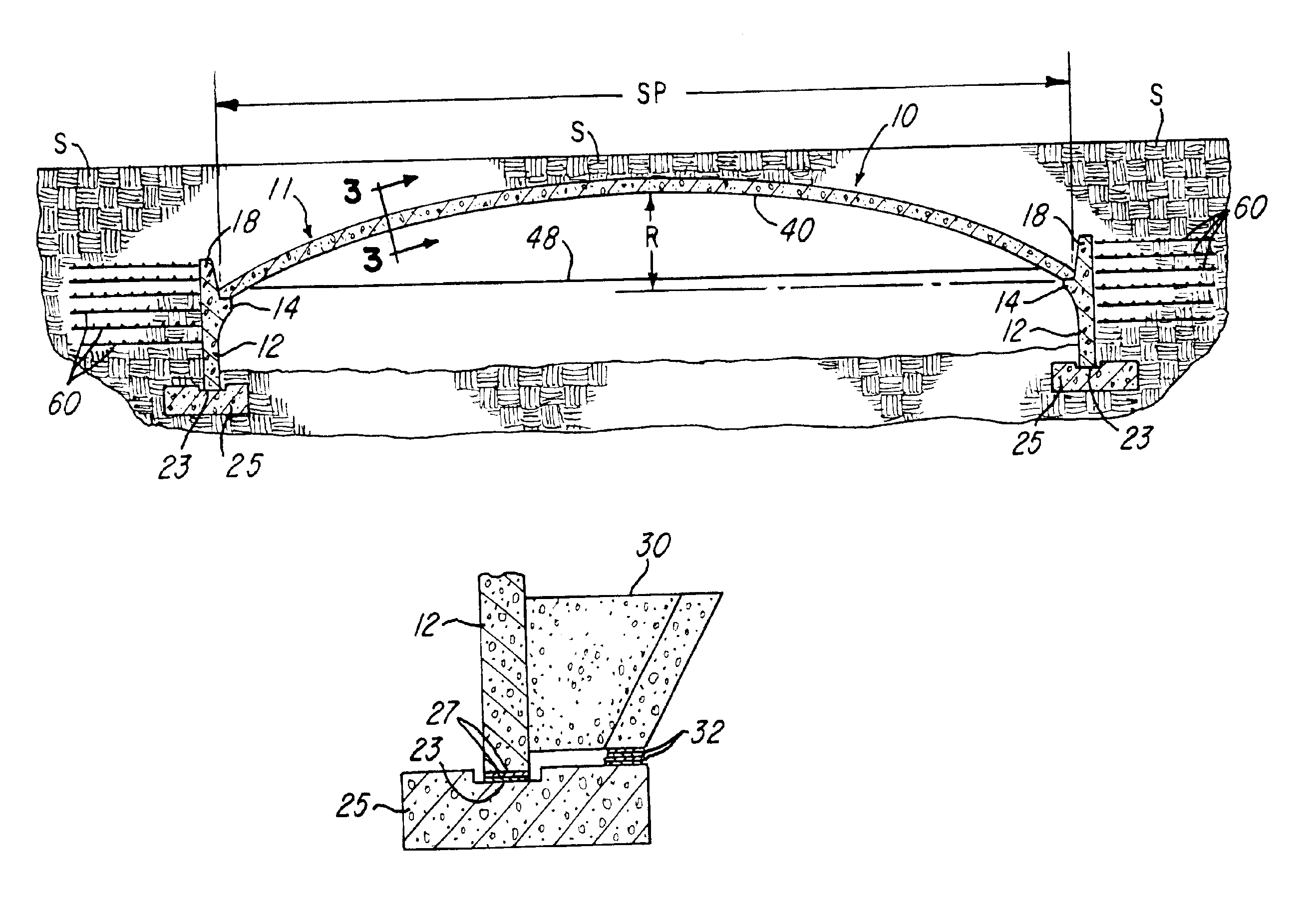
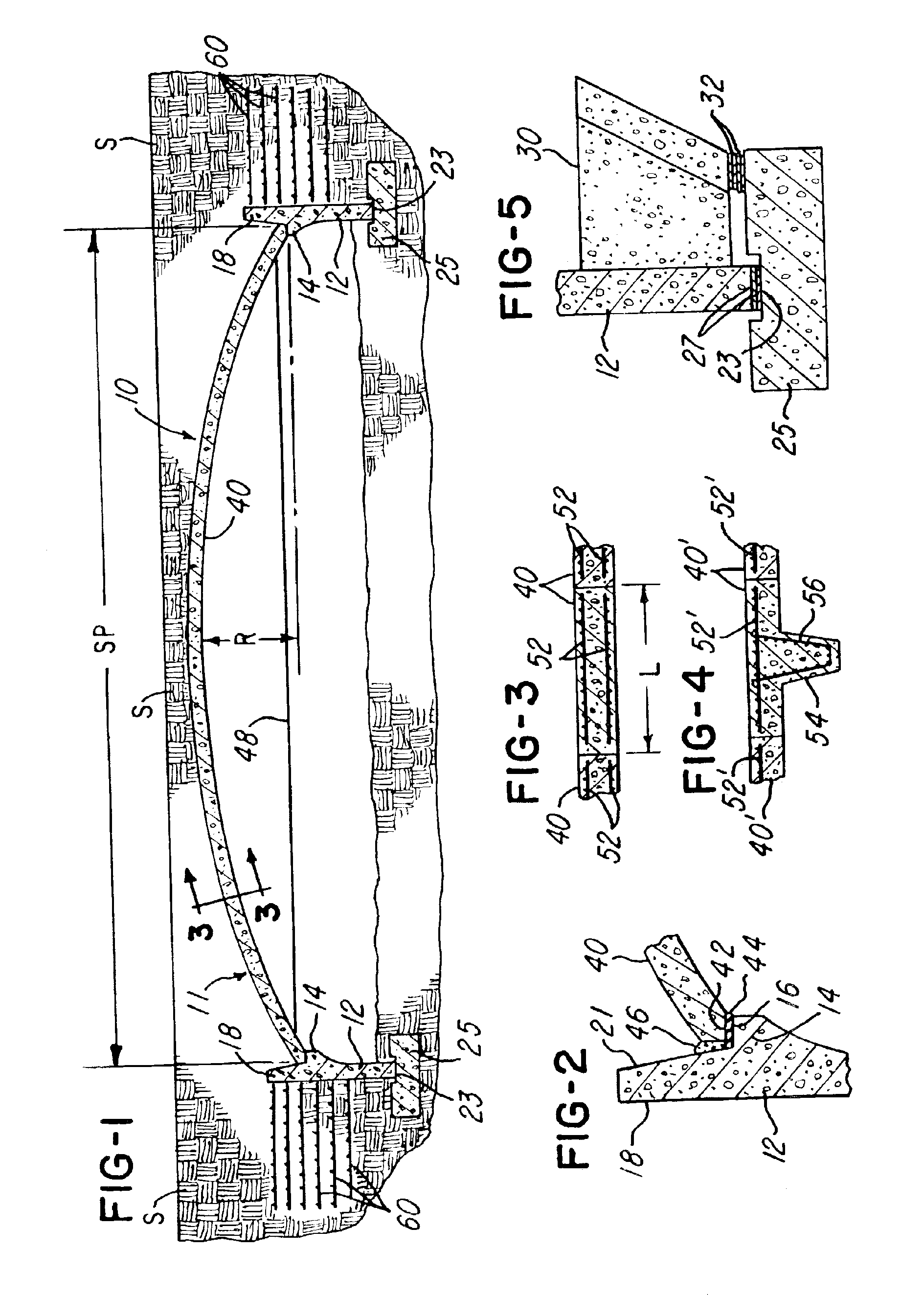
The present invention is directed to a precast concrete culvert system wherein each unit has a three piece construction, including a pair or set of precast concrete side wall sections. The wall sections are mounted on and supported by corresponding concrete footers and have inwardly projecting and opposing support steps or surfaces which forms seats for opposite ends of a precast concrete arched top wall section. The side wall sections include extension portions which project upwardly substantially above the support surfaces for the ends of the top wall section for substantially increasing the capacity of the side wall sections to resist thrust from the arched top wall section. A temporary cable ties or connects opposite end portions of the arched top wall section during shipping and handling and is removed after the side wall sections are backfilled with compacted soil.
Precast concrete anchor members, such as the anchor members disclosed in above mentioned U.S. Pat. No. 4,993,872, may be attached to the side wall sections and project into the backfilled soil, and one or more shims may be positioned between the anchor member and the supporting footer for each side wall section to obtain horizontal and vertical alignment of the side wall sections before receiving the top wall sections. The compacted backfill soil for the side wall sections, including the soil adjacent the extension portions, may be stabilized by vertically spaced layers of soil reinforcement members or grids for lowering the stress levels in each three section precast unit in order to reduce the concrete reinforcement required in the unit and / or the wall thickness of each precast section.

Problems solved by technology

For example, with a culvert system having a span above 48 feet, the weight, height and length of each one-piece culvert unit present problems with shipping the unit along a roadway on a low bed semi-trailer.

Method used


Image

  • Precast concrete culvert system
  • Precast concrete culvert system

Examples


Embodiment Construction

FIG. 1 illustrates a concrete culvert system 10 constructed in accordance with the invention and including one or more longitudinally aligned three piece precast culvert units 11 each having a pair of generally vertical and parallel spaced precast side wall sections 12 which have suitable embedded reinforcement members (not shown). Each wall section 12 has an intermediate step portion 14 of greater thickness and forming a supporting surface or seat 16. Each wall section 12 also includes an upwardly projecting an integrally cast extension portion 18 having an inclined inner surface 21 which projects upwardly and outwardly from the surface or seat 16. The bottom edge of each wall section 12 seats within a horizontal recess 23 formed within the top of a concrete footer 25 which is preferably cast in place and has embedded reinforcing members or rods (not shown). As shown in FIG. 5, one or more shims 27 may be placed within the recess 23 under the bottom surface of each wall section 12 ...


PUM


Abstract

A three piece concrete culvert system includes a set of horizontally spaced precast side wall sections having inwardly projecting and opposing steps or surfaces which support opposite ends of a precast arched top wall section. The side wall sections include extension portions which project substantially above the ends of the top wall section for increasing the capacity of the side wall sections to resist thrust from the top wall section. Vertically spaced and generally horizontal layers of soil reinforcement members or grids may be positioned within the soil backfilled adjacent the outer surfaces of the side wall sections, and precast concrete anchor members may be attached to the side wall sections above supporting footers for the side wall sections. Shims are used between the footers and the anchor members for temporarily positioning and aligning the side wall sections before receiving the top wall section.

Description

BACKGROUND OF THE INVENTIONIn a precast open bottom culvert system, for example, as disclosed in U.S. Pat. No. 4,993,872 which issued to the assignee of the present invention, the handling and shipping restrictions with respect to weight, height and width of each precast open bottom one-piece culvert unit has limited the maximum span for a culvert system. For example, with a culvert system having a span above 48 feet, the weight, height and length of each one-piece culvert unit present problems with shipping the unit along a roadway on a low bed semi-trailer.SUMMARY OF THE INVENTIONThe present invention is directed to a precast concrete culvert system wherein each unit has a three piece construction, including a pair or set of precast concrete side wall sections. The wall sections are mounted on and supported by corresponding concrete footers and have inwardly projecting and opposing support steps or surfaces which forms seats for opposite ends of a precast concrete arched top wall ...

Claims


Application Information

Patent Timeline
IPC IPC(8): E01F5/00E02D29/045E02D29/05E02D29/02
CPCE01F5/005E02D29/05E02D29/0241
Inventor LOCKWOOD, WILLIAM D.
Owner CONTECH ENGINEERED SOLUTIONS
Learn More