Speed governor

a speed governor and speed technology, applied in the direction of wind motor control, motors, mechanical equipment, etc., can solve the problems of significant loss of efficiency, significant change in drilling resistance, and significant reduction of the flow of motive fluid through the motor or turbine, so as to achieve convenient and efficient manner

Inactive Publication Date: 2005-02-15
ROTECH GROUP
View PDF9 Cites 60 Cited by
  • Summary
  • Abstract
  • Description
  • Claims
  • Application Information

AI Technical Summary

Benefits of technology

It has now been found that over-speeding can be controlled in a particularly convenient and efficient manner

Problems solved by technology

It is a particular problem with down-hole drilling that the material being drilled through can be subject to frequent and/or large changes in hardness and/or other properties resulting in significant changes in drilling resistance.
In the case of both such conventional speed governors and eddy cu

Method used


Image

  • Speed governor
  • Speed governor
  • Speed governor

Examples


Embodiment Construction

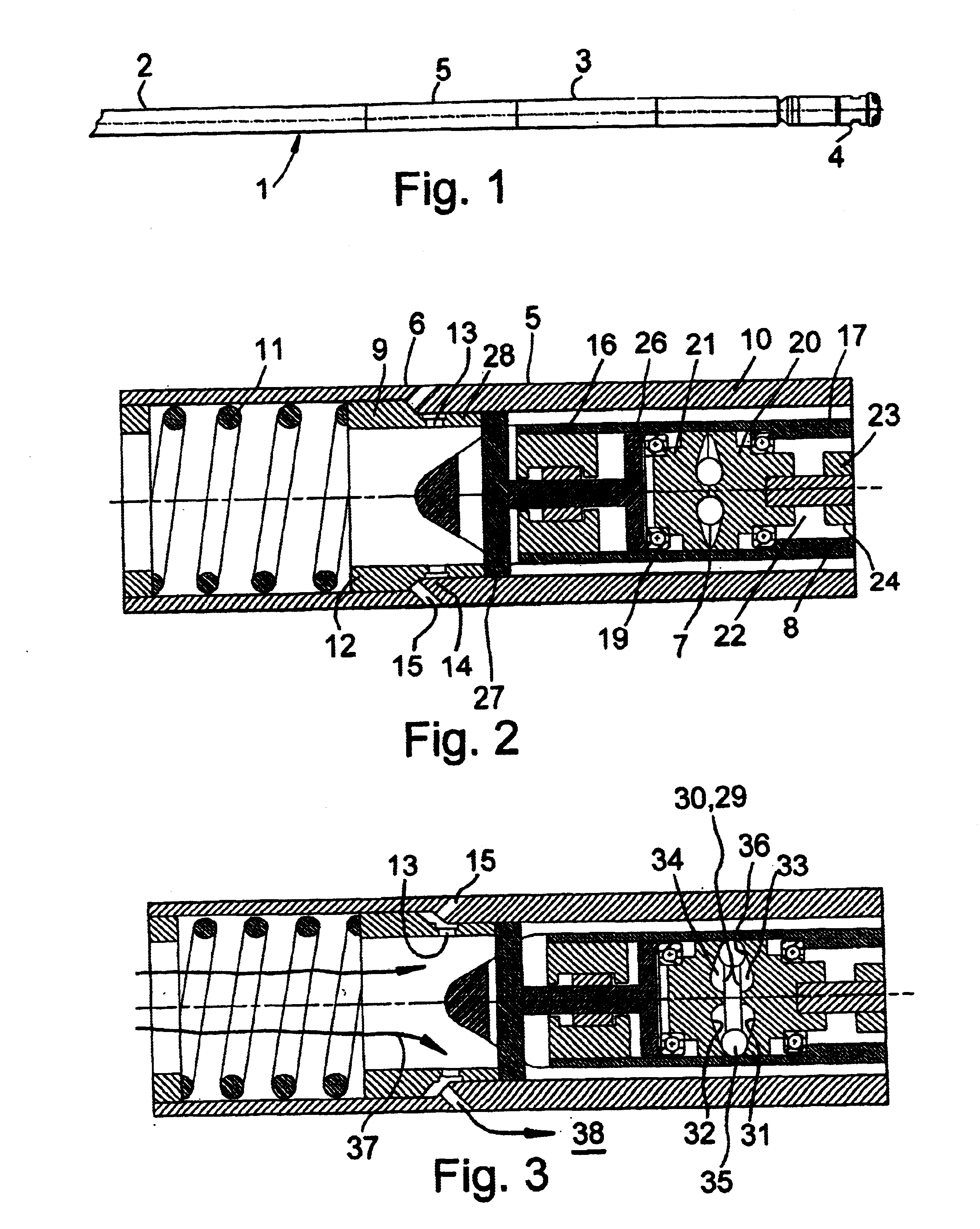
FIG. 1 shows a drilling apparatus 1 comprising a drill string 2 supporting a down-hole turbine 3 used for driving a drilling bit 4 and provided with a speed governor 5. Conveniently the turbine is similar to that disclosed in our earlier patent publication no. WO 00 / 08293 (the contents of which are hereby incorporated herein), and especially as illustrated in the embodiments illustrated therein.

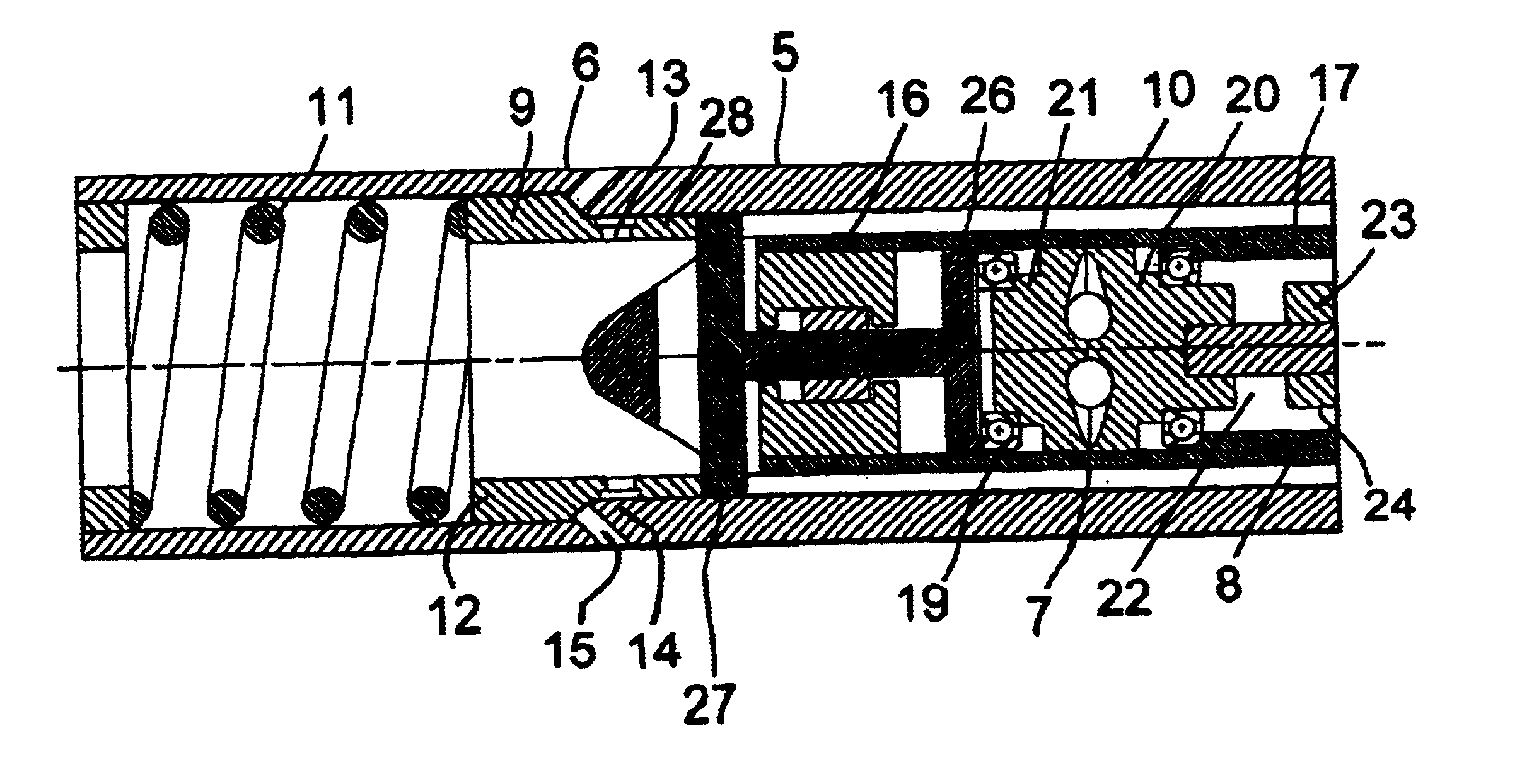
FIG. 2 shows a speed governor 5 comprising a dump valve 6 provided with an actuator 7 mounted at the upper end 8 of a down-hole turbine 3. In more detail the dump valve 6 comprises an inner sleeve member 9 mounted inside an outer casing extension 10 of the turbine 3 for sliding reciprocal movement. A pre-loaded helical spring 11 is mounted inside the outer casing extension 10 for acting against the upper end 12 of the sleeve 9 urging it into its closed position as shown in FIG. 2. The sleeve 9 has a series of ports 13 which are occluded by part 14 of the outer casing extension 10 in the close...


PUM


Abstract

The present invention provides a speed governor (5) suitable for use in a fluid driven down-hole tool (3). The speed governor comprises an actuator (7) operatively coupled to a motive fluid flow control valve (6). The actuator is and arranged so as to be activatable, directly or indirectly, in response to the running speed of the tool (3), for opening of the control valve (6) with increasing rotational speed of the motor (3) above a predetermined speed limit thereby to limit the rotational speed of the downhole tool (3).

Description

BACKGROUND OF THE INVENTIONThe present invention relates to speed governors suitable for use in controlling the speed of high speed turbines and other fluid driven motors, and especially those used in down-hole drilling applications and the like.It is a particular problem with down-hole drilling that the material being drilled through can be subject to frequent and / or large changes in hardness and / or other properties resulting in significant changes in drilling resistance. When there is a more or less sudden reduction in drilling resistance, which is especially large when the drilling bit lifts off from the bottom of the borehole for any reason, there is a tendency for the motor to speed up veiy quickly and dramatically—typically in as little as 20 to 100 milliseconds. In the past, prevention of such over-speeding has been attempted by very careful control of the drilling operation to try to minimize any possible lift off, and / or to use braking systems such as eddy current brakes. C...

Claims


Application Information

Patent Timeline
IPC IPC(8): E21B21/10E21B21/00E21B4/02E21B4/00E21B44/00
CPCE21B4/02E21B44/005E21B21/103
Inventor VAN DRENTHAM-SUSMAN, HECTOR F. A.STEWART, KENNETH RODERICKNEILSON, RICHARD D.STEWART, DONALDHARRIS, GARY L.
Owner ROTECH GROUP
Why Eureka
Try Eureka