Modular system

Inactive Publication Date: 2005-02-15
ABB PATENT GMBH
View PDF13 Cites 3 Cited by
  • Summary
  • Abstract
  • Description
  • Claims
  • Application Information

AI Technical Summary

Benefits of technology

In this way, a high degree of variability is achieved with a small number of plug-in contacts in every plug-in connection, and a free choice of slots is made possible for pluggable electrical units of an identical mechanical type of construction with different electrical interfaces designed for the plug-in contact device.
This advantageously makes it possible for non-system pluggable electrical units to be integrated, in that the individual configuration data of the pluggable electrical unit are read out and the communication lines routed via the second group of plug-in contacts are configured individually for this slot in a way corresponding to the configuration data read.

Problems solved by technology

Such backplane wiring in the manner of a parallel bus no longer allows individualizing of the electrical interface of the pluggable electrical units that is designed for the plug-in contact device, since plug-in contacts of the same name would be wired to different types of signals, which may also differ in the direction of signal transmission.
If the free choice of slots is maintained for all the pluggable electrical units, the number of necessary plug-in contacts increases in proportion to the degree of individualization of the pluggable electrical units, and so does the complexity of the backplane wiring.
This additional complexity is felt to be disadvantageous.
In addition, the overall size of the plug-in connector increases with the number of pins.

Method used


Image

  • Modular system
  • Modular system
  • Modular system

Examples


Embodiment Construction

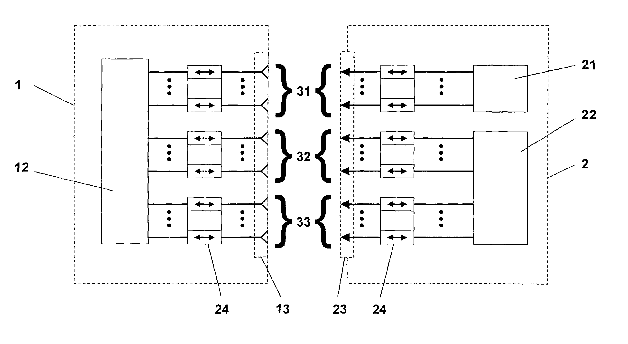
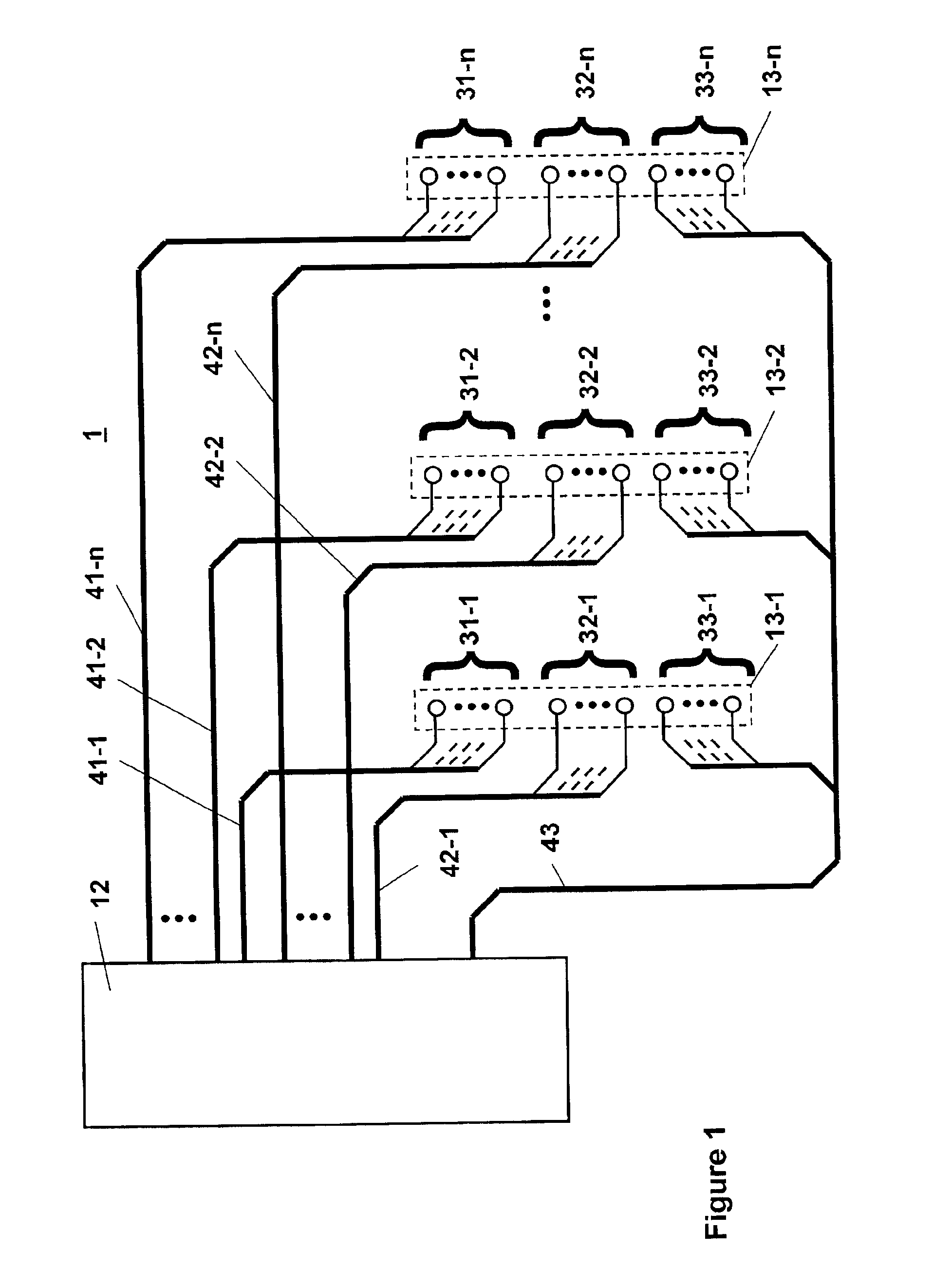
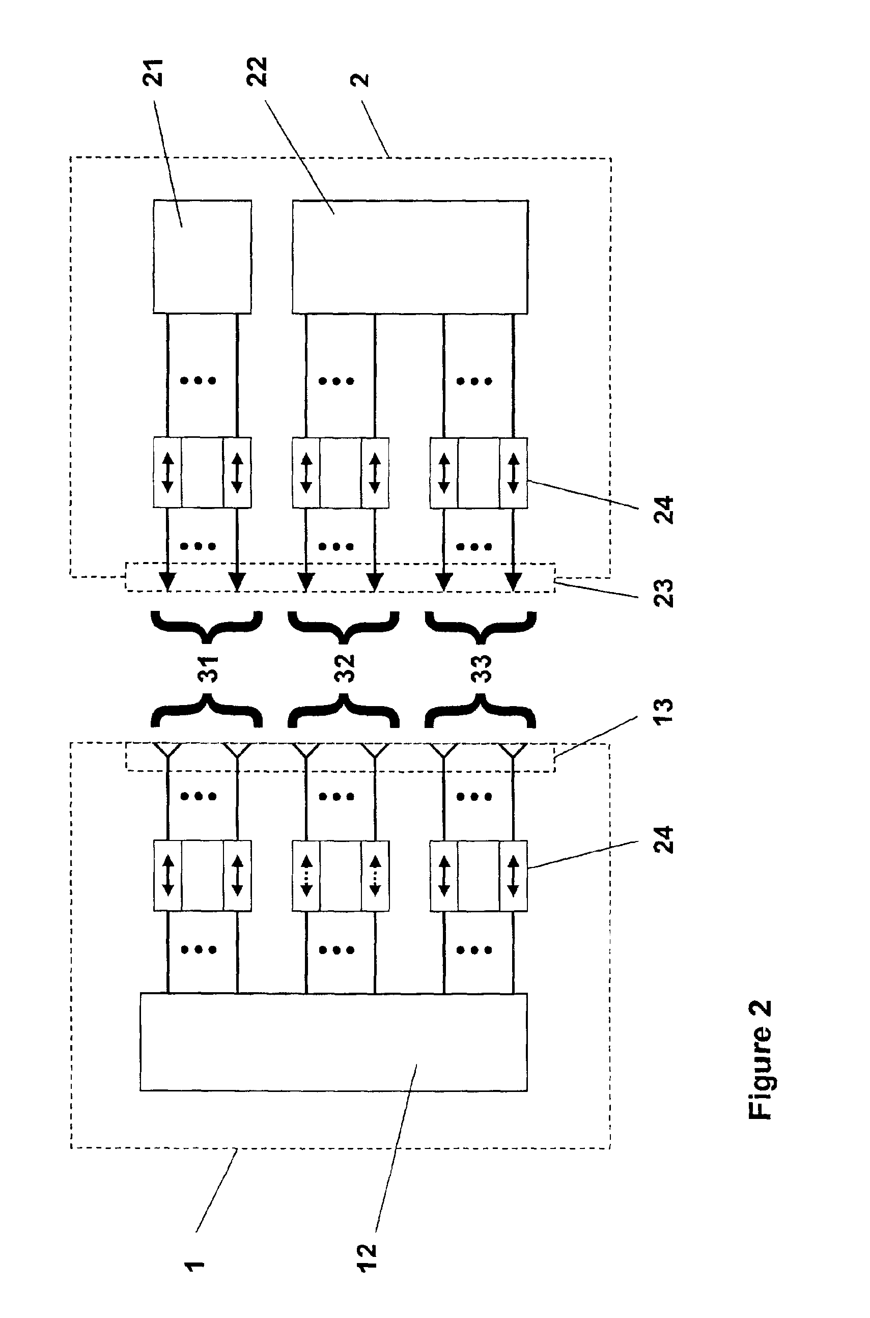
Represented in FIG. 1 is a basic diagram of the wiring of a base element 1 with n slots each for receiving a pluggable electrical unit. Each slot is provided with a multi-pin mating plug-in contact device 13-1, 13-2 to 13-n. The mating plug-in contact devices 13-1, 13-2 to 13-n are of the same type and have plug-in contacts which are divided into groups. Plug-in contacts of the same name of each mating plug-in contact device 13-1, 13-2 to 13-n belong to the same group.

Connected to a first group 31-1, 31-2 to 31-n of plug-in contacts of the mating plug-in contact devices 13-1, 13-2 to 13-n there are in each case permanently configured lines 411, 41-2 to 41-n for the identification of the pluggable electrical unit at the respective slot. For each plug-in contact of the first group 31-1, 31-2 to 31-n of plug-in contacts of each mating plug-in contact device 13-1, 13-2 to 13-n, the logical signal assignments and the directions of signal transmission are permanently prescribed and are id...


PUM


Abstract

The invention relates to a modular system comprising an electrical base unit (1) with a plurality of slots each for receiving a pluggable electrical unit (2), each pluggable electrical unit (2) being connected to the base unit (1) by means of a multi-pin plug-in connection comprising a plug-in contact device (23) and a mating plug-in contact device (13) and the base unit (1) being provided with signal processing means (12). For this purpose, it is proposed to divide the plug-in contacts of the multi-pin plug-in connection (13, 23) into at least two groups (31, 32), a first group (31) of plug-in contacts being intended for the connection of permanently configured lines for the identification of the pluggable electrical unit (2) and a second group (32) of plug-in contacts being intended for the connection of freely configurable lines for the communication of the pluggable electrical unit (2) with the base unit (1), the direction of signal transmission and the logical signal assignment of these lines being predeterminable slot-specifically in accordance with the identity of the pluggable electrical unit (2) and able to be set as prescribed by the signal processing means (12) of the base unit (1).

Description

BACKGROUND OF THE INVENTIONThe invention relates to a modular system comprising an electrical base unit with a plurality of slots each for receiving a pluggable electrical unit, each pluggable electrical unit being electrically connected to the base unit by means of a multi-pin plug-in connection comprising a plug-in contact device and a mating plug-in contact device.Complex electrical engineering systems, in particular in measuring and control technology and in telecommunications, are often of a modular construction. This involves a large number of electrical units being accommodated in an enclosure of an electrical base unit in a pluggable manner.The base unit is often provided with rear wiring which connects all the mating plug-in contact devices, and may be configured as a cable harness, as a winding bridge or as a backplane. To allow a free choice of the slot for any desired pluggable unit, in this case plug-in contacts of the same name of each mating plug-in contact device are...

Claims


Application Information

Patent Timeline
IPC IPC(8): H01R12/16H01R12/00H05K7/14H01R13/46H01R12/50
CPCH05K7/1459H01R23/68H01R13/465
Inventor GOERS, ANDREASMICHEL, HELMUTBLEIL, REINER
Owner ABB PATENT GMBH
Why Eureka
Try Eureka