Power source apparatus

a technology for power source equipment and switching means, which is applied in the direction of emergency power supply arrangements, instruments, process and machine control, etc., can solve the problems of large number of wirings, complicated wiring, and complicated wiring, and achieve the effect of improving the switching operation of the switching means associated with the individual power source units

Inactive Publication Date: 2005-02-15
ORMON CORP
View PDF5 Cites 34 Cited by
  • Summary
  • Abstract
  • Description
  • Claims
  • Application Information

AI Technical Summary

Benefits of technology

[0080]Therefore, according to the power source apparatus of the present invention, since the switch performs a switching operation when the power source units connect mutually, it is constructed so that an adjusting operation of the adjusting means inside the individual power source units becomes the off control automatically and on control of the adjusting operation of the adjusting means is performed in response to a switching manipulation of the switching means, so that the switching operation of the switching means associated with the individual power source units is improved.

Problems solved by technology

Particularly, the number of wirings is large in connections of the additional function apparatus having plural additional functions and the wiring has become complicated.
However, according to the conventional power source apparatus, since this power source apparatus is connected to the additional function apparatus through external wiring, in connections of the additional function apparatus having plural additional functions, the wiring becomes complicated and is not practical and also because of the complicated wiring, it is susceptible to noise and a malfunction tends to occur and commercialization is obstructed.

Method used


Image

  • Power source apparatus
  • Power source apparatus
  • Power source apparatus

Examples


first embodiment

[0129](First Embodiment)

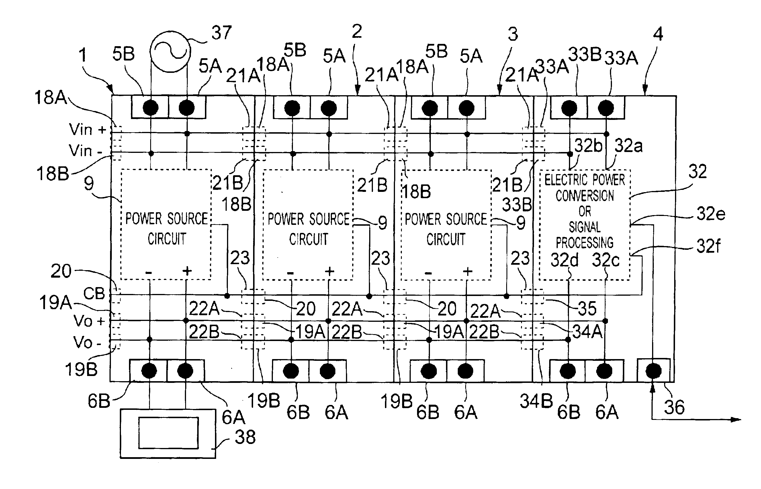
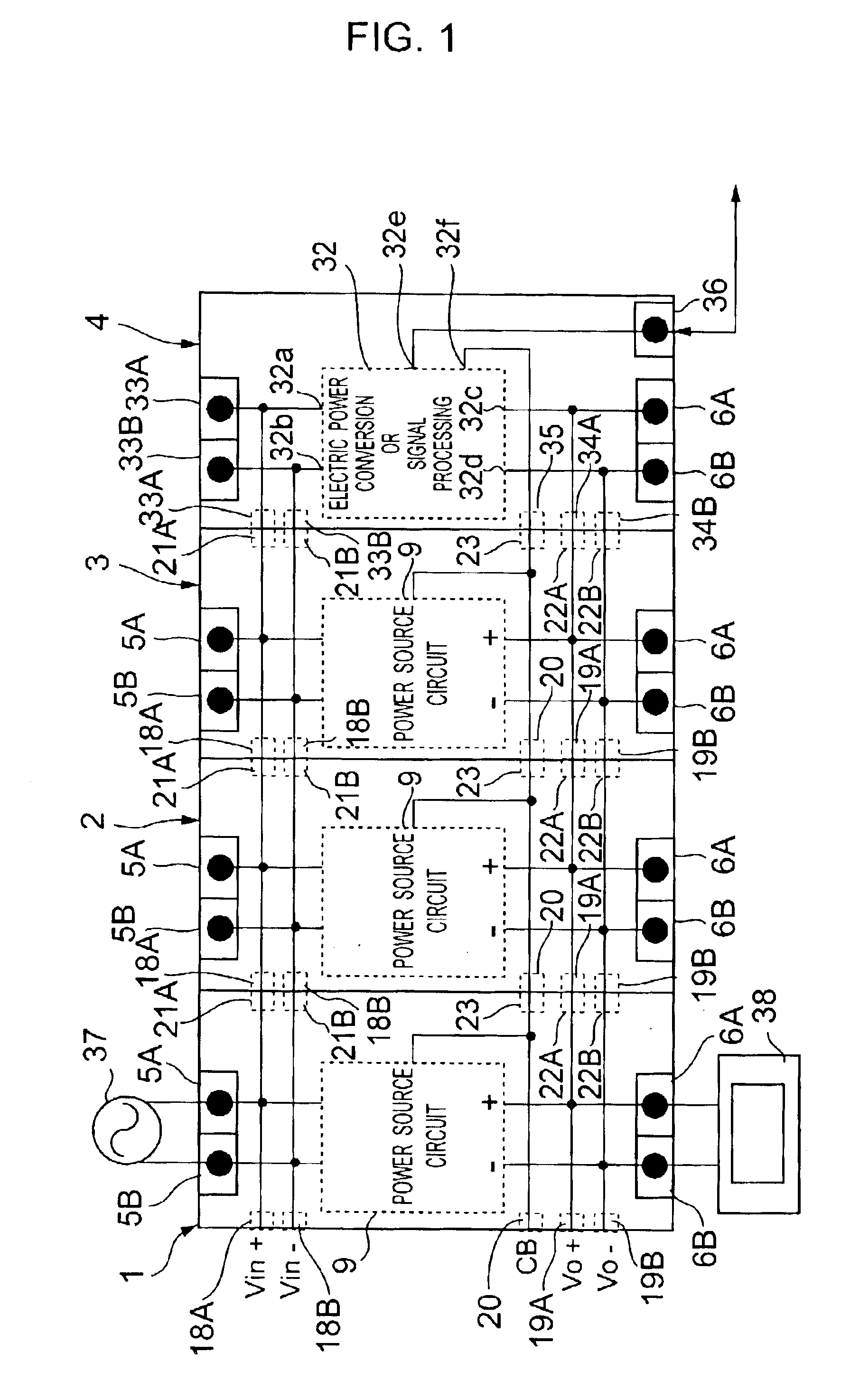
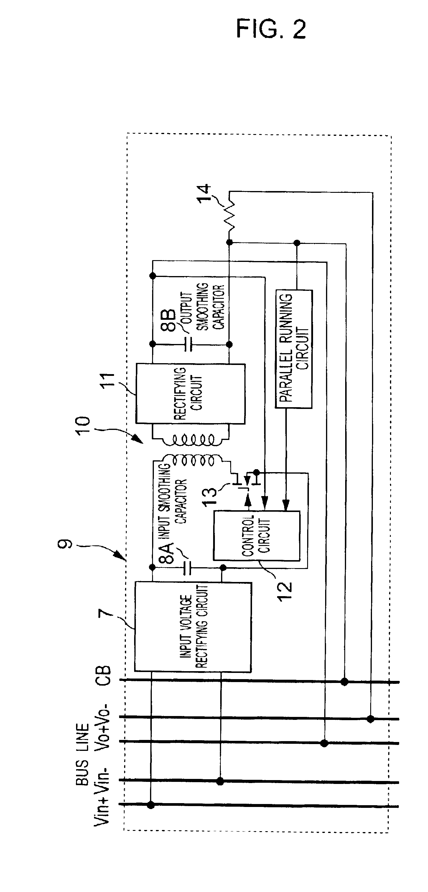
[0130]A first embodiment of a power source apparatus according to the present invention is shown in FIGS. 1 and 2.

[0131]In these drawings, numeral 1 is a first power source unit, and numeral 2 is a second power source unit, and numeral 3 is a third power source unit, and numeral 4 is an additional function unit. Then, connections between the first power source unit 1 and the second power source unit 2 and between the second power source unit 2 and the third power source unit 3 are respectively made by connector connection means and a module power source is formed of these units.

[0132]The first power source unit 1 is a switching power source, for example, for input of 100 to 240 V AC, output of 24 V DC and output of 2.5 A, 60 W in which a required part for power source circuit is built into a rectangular parallelepiped-shaped casing with a front panel shape formed in a longitudinally elongated rectangle.

[0133]Then, AC input terminals 5A, 5B, DC output terminal...

second embodiment

[0155](Second Embodiment)

[0156]A second embodiment of a power source apparatus according to the present invention is shown in FIG. 3.

[0157]In FIG. 3, numeral 41 is a first power source unit, and numeral 42 is a second power source unit, and numeral 43 is a third power source unit, and numeral 44 is an additional function unit. Then, connections between the first power source unit 41 and the second power source unit 42 and between the second power source unit 42 and the third power source unit 43 are respectively made by connector connection means and a module power source is formed of these units.

[0158]Then, a power source circuit 9-1, AC input terminals 5A, 5B, DC output terminals 6A, 6B, AC input bus lines (Vin+), (Vin−) and DC output bus lines (Vo+), (Vo−) are placed in the first, second, third power source units 41, 42, 43.

[0159]The AC input terminals 5A, 5B are installed in the upper portion of a front panel and guides an external commercial AC of 100 to 240 V AC to the power s...

third embodiment

[0174](Third Embodiment)

[0175]A third embodiment of a power source apparatus according to the present invention is shown in FIG. 4.

[0176]In FIG. 4, numeral 51 is a first power source unit, and numeral 52 is a second power source unit, and numeral 53 is a third power source unit, and numeral 54 is an additional function unit. Then, connections between the first power source unit 51 and the second power source unit 52 and between the second power source unit 52 and the third power source unit 53 are respectively made by connector connection means and a module power source is formed of these units.

[0177]Then, a power source circuit 9-1, AC input terminals 5A, 5B, DC output terminals 6A, 6B, AC input bus lines (Vin+), (Vin−) and DC output bus lines (Vo+), (Vo−) are placed in the first, second, third power source units 51, 52, 53.

[0178]The AC input terminals 5A, 5B are installed in the upper portion of a front panel and guides an external commercial AC of 100 to 240 V AC to the power sou...


PUM


Abstract

A power source apparatus with a saving in wiring, large noise immunity and an additional function is achieved by connecting AC input bus lines (Vin+), (Vin−), DC output bus lines (Vo+), (Vo−) and a current balance signal bus line (CB) for connecting first, second, third power source units 1, 2, 3 through connectors to form a module power source and connecting an additional function unit 4 for adding a predetermined additional function to the module power source using the bus lines to this module power source through a connector.

Description

TECHNICAL FIELD[0002]The present invention relates to a power source apparatus constructed so that a module power source formed by connecting at least one or more power source units is provided and an additional function unit having a predetermined function is added in order to add the predetermined function to this module power source.BACKGROUND ART[0003]Conventionally, in the case of connecting an additional function apparatus for adding some additional function to a power source apparatus, the power source apparatus has been connected to the additional function apparatus through external wiring. Particularly, the number of wirings is large in connections of the additional function apparatus having plural additional functions and the wiring has become complicated.[0004]For example, in the case of building a power source system having a backup function using a battery, as shown in FIG. 46, it was necessary to externally wire DC output terminals 801A, 801B of a power source apparatu...

Claims


Application Information

Patent Timeline
Patent Type & Authority Patents(United States)
IPC IPC(8): H02J9/06H02J1/10H02M3/156
CPCH02J1/102H02M3/156H02J9/061H02M3/28
Inventor MURABAYASHI, HARUYASUHORIE, TAKASHIISOZUMI, MASASHITSUBOTA, YASUHIROOOBA, TSUNETOSHIKOBORI, HIDEKIOOTOMO, TAKATOSHIMARUMO, KATSUYAYAMAMOTO, TETSUYA
Owner ORMON CORP
Why Eureka
Try Eureka