Interconnecting ring and wire guide

a technology of interconnection ring and wire guide, which is applied in the direction of dynamo-electric machines, magnetic circuit shape/form/construction, structural associations, etc., can solve the problems of reliability problems, low cost of approach, and degradation of electrical characteristics of electric machines

Inactive Publication Date: 2005-02-15
NIDEC MOTOR CORP
View PDF35 Cites 83 Cited by
  • Summary
  • Abstract
  • Description
  • Claims
  • Application Information

AI Technical Summary

Benefits of technology

One phase wiring approach involves manually interconnecting the stator segment assemblies using insulated winding wire. This approach has a relatively high cost. In addition, loose phase wires laying randomly on top of coils of the electric machine may cause degradation of the electrical characteristics of the electric machine. Lack of adequate strain relief for jumper wires and lead wires may cause reliability problems. Solutions include resin potting the phase wiring and / or using single or multi-strand insulated phase wires. Other solutions include using a printed circuit board instead of phase wires, which has a relatively high cost.

Problems solved by technology

This approach has a relatively high cost.
In addition, loose phase wires laying randomly on top of coils of the electric machine may cause degradation of the electrical characteristics of the electric machine.
Lack of adequate strain relief for jumper wires and lead wires may cause reliability problems.
Other solutions include using a printed circuit board instead of phase wires, which has a relatively high cost.

Method used


Image

  • Interconnecting ring and wire guide
  • Interconnecting ring and wire guide
  • Interconnecting ring and wire guide

Examples


Embodiment Construction

The following description of the preferred embodiment(s) is merely exemplary in nature and is in no way intended to limit the invention, its application, or uses. For purposes of clarity, the same reference numbers will be used in the drawings to identify similar elements.

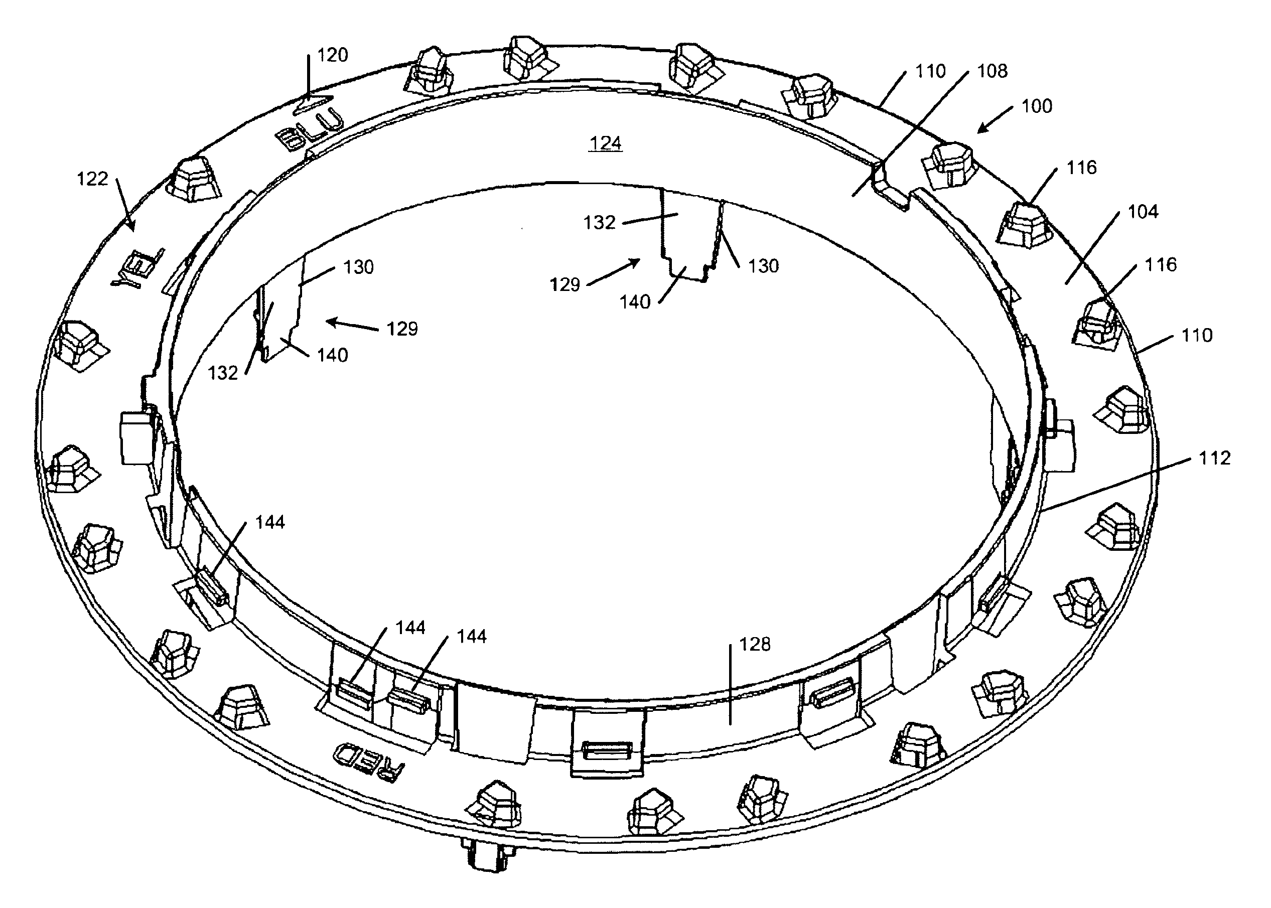
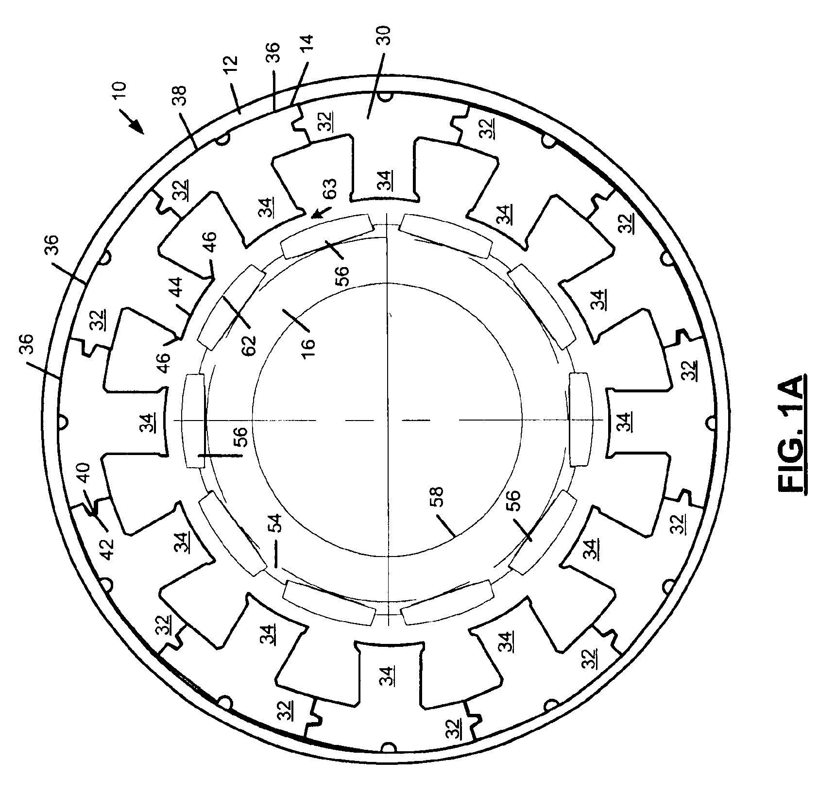
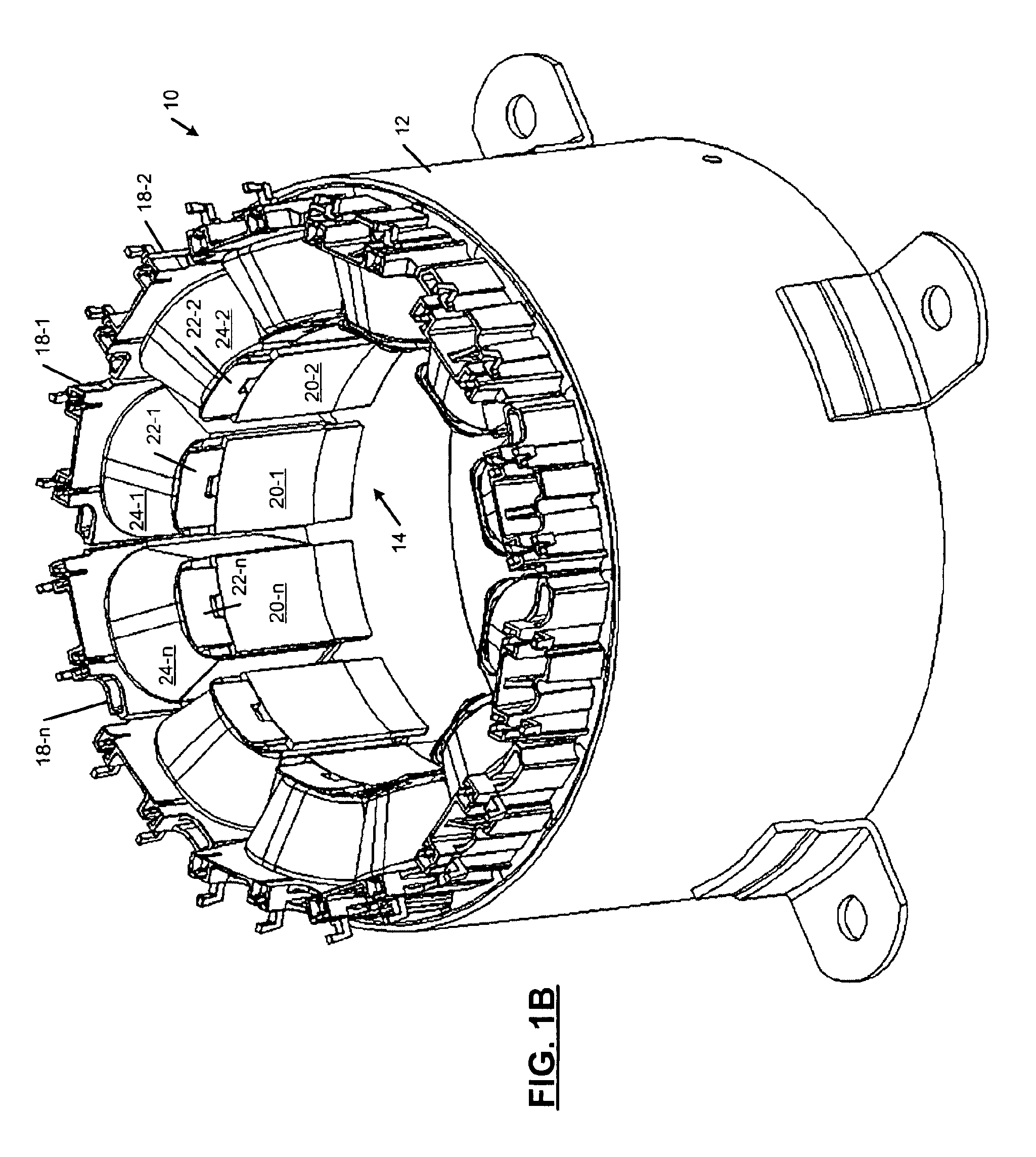
The interconnecting ring and wire guide according to the present invention improves phase wiring connections between segmented stator assemblies in an electric machine. The interconnecting ring and wire guide also retains individual connecting phase wires, separates them, and maintains axial and radial positioning of the phase wires relative to the stator.

The interconnecting ring and wire guide includes wire dividers that separate the phase wires. The wire dividers prevent the phase wires from entering the stator bore. The interconnecting ring and wire guide includes positioning indicia to locate the interconnecting ring and wire guide relative to the electric machine. The location indicia also may include a wiring...


PUM


Abstract

An interconnecting ring and wire guide for an electric machine includes an annular radial ring having a radially inner edge and a radially outer edge. An axial ring projects axially from the radially inner edge of the annular radial ring. A guide positioner positions the annular radial ring and the axial ring relative to the electric machine. Wire dividers are located on a radially outer surface of the radial ring. The wire dividers include a plurality of circumferential projections that are formed on the radially outer surface of the radial ring. A plurality of wire guides are located adjacent to a radially outer edge of the annular radial ring. Indicia on an outer surface of the annular radial ring identifies at least one of a mounting position for the interconnecting ring and wire guide and a wiring schematic for phases wiring of the electric machine.

Description

FIELD OF THE INVENTIONThe present invention relates to electric machines, and more particularly to an interconnecting ring and wire guide for an electric machine.BACKGROUND OF THE INVENTIONElectric machines, such as motors and generators, typically include a stator that is mounted inside a housing and a rotor that is supported for rotation relative to the stator. Some brushless permanent magnet electric machines include a segmented stator with a plurality of stator segment assemblies. The stator segment assemblies typically include a stator core, an end cap assembly, and winding wire. Some switched reluctance electric machines also include a segmented stator.The winding wires of the stator segment assemblies are wound around the stator core and the end cap assembly. Opposite ends of the winding wire are connected to insulation displacement connectors (IDC) or wound around terminals that are integrated with the end cap assembly. Additional wire connects the IDC or wiring terminals to...

Claims


Application Information

Patent Timeline
Patent Type & Authority Patents(United States)
IPC IPC(8): H02K3/52H02K3/46
CPCH02K3/522H02K2203/06H02K2203/03H02K1/12H02K3/52
Inventor MICHAELS, PAUL G.SHEERAN, KENT A.WALLACE, CRAIG E.HILTON, DANIEL E.HARTSFIELD, JR., RICHARD E.
Owner NIDEC MOTOR CORP
Why Eureka
Try Eureka