Systems and methods for overcoming stiction

Inactive Publication Date: 2005-02-15
ALTERA CORP
View PDF16 Cites 69 Cited by
  • Summary
  • Abstract
  • Description
  • Claims
  • Application Information

AI Technical Summary

Benefits of technology

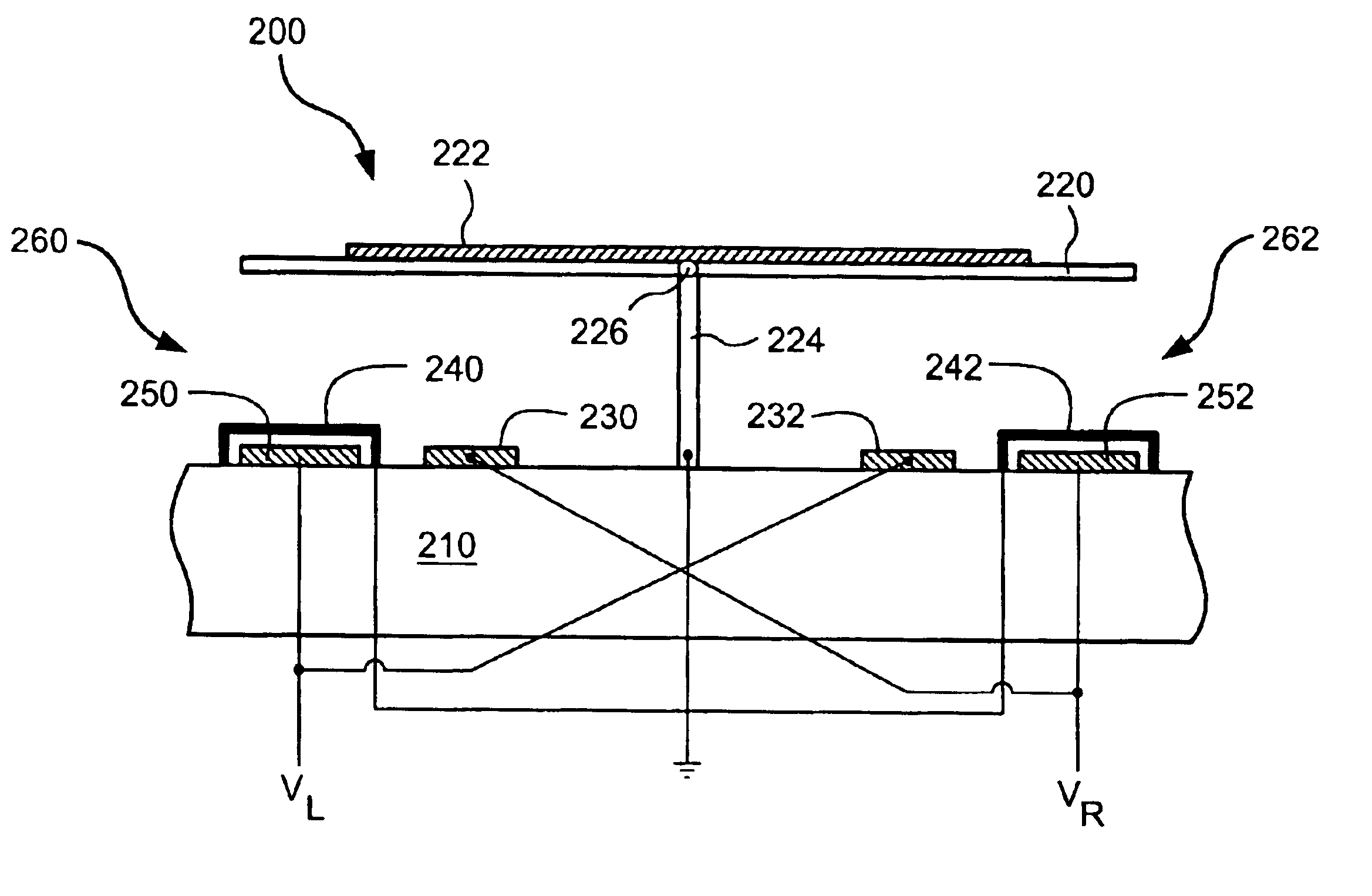
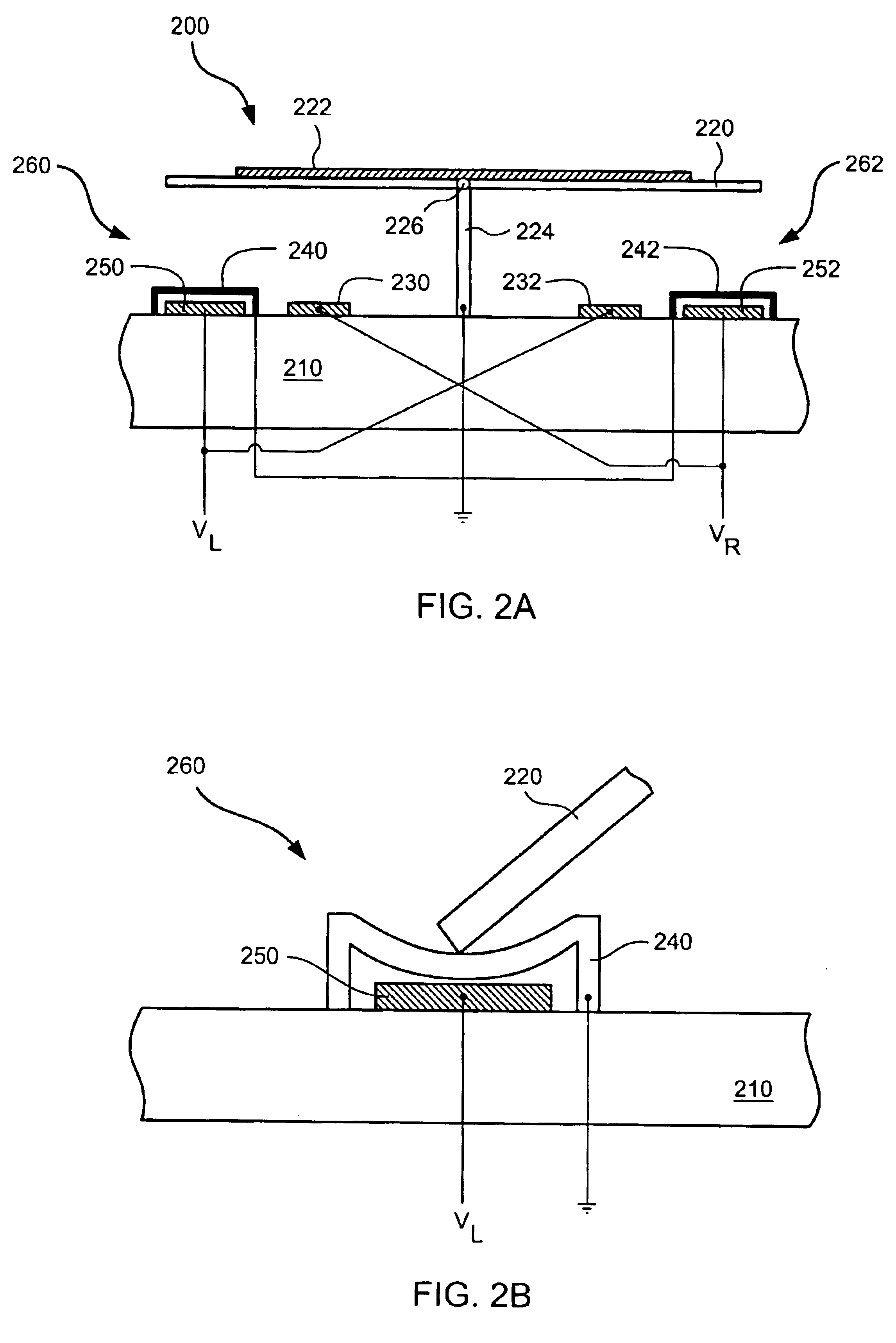
Yet other embodiments of the present invention provide systems capable of overcoming stiction forces. Such systems can include a base layer with a structural plate supported above the base layer by a pivot. The structural plate is moveable along a movement path until it contacts a stop located at a position along the movement path. Stiction forces can result at the contact between the structural plate and the stop. To overcome the stiction forces, a local vibration element is provided at or near the contact between the stop and the structural plate. The vibration element provides local vibration sufficient to overcome the stiction forces.

Problems solved by technology

In yet other embodiments, the local vibration is caused by activating and deactivating an actuator such that a serpentine structure or other spring structure is repetitively moved resulting in a vibration.

Method used


Image

  • Systems and methods for overcoming stiction
  • Systems and methods for overcoming stiction
  • Systems and methods for overcoming stiction

Examples


third embodiment

a wavelength router, designated 10″, is illustrated with the schematic top view shown in FIG. 9. This embodiment is a further folded version of the embodiment of FIGS. 11A-11C, shown as a solid glass embodiment that uses a concave reflector 40 in place of lens 20 of FIGS. 11A-11C or lenses 20a and 20b of FIGS. 12A-12B. Light entering the wavelength router 10″ from input port 12 forms diverging beam 18, which includes the different spectral bands. Beam 18 encounters concave reflector 40, which collimates the light and directs it to reflective diffraction grating 25, where it is dispersed so that collimated beams at different wavelengths are directed at different angles back towards concave reflector 40. Two such beams are shown explicitly, one in solid lines and one in dashed lines. The beams then encounter retroreflectors 30 and proceed on a return path, encountering concave reflector 40, reflective grating 25′, and concave reflector 40, the final encounter with which focuses the be...


PUM


Abstract

A number of methods and systems for overcoming stiction are provided. The systems include electro-mechanical systems capable of exerting a variety of forces upon areas prone to stiction. The systems can be MEMS arrays or other types of devices where stiction related forces occur. The methods include a variety of ways of causing movement in areas prone to stiction forces. Such movement can be vibrational in nature and is sufficient to overcome stiction, allowing a trapped element to be moved to a desired location.

Description

BACKGROUND OF THE INVENTIONThis invention relates generally to the field of micro-electrical-mechanical systems (MEMS), and in particular, to improved MEMS devices and methods for their use with fiber-optic communications systems.The Internet and data communications are causing an explosion in the global demand for bandwidth. Fiber optic telecommunications systems are currently deploying a relatively new technology called dense wavelength division multiplexing (DWDM) to expand the capacity of new and existing optical fiber systems to help satisfy this demand. In DWDM, multiple wavelengths of light simultaneously transport information through a single optical fiber. Each wavelength operates as an individual channel carrying a stream of data. The carrying capacity of a fiber is multiplied by the number of DWDM channels used. Today DWDM systems employing up to 80 channels are available from multiple manufacturers, with more promised in the future.In all telecommunication networks, ther...

Claims


Application Information

Patent Timeline
Patent Type & Authority Patents(United States)
IPC IPC(8): H02N1/00B81B3/00G02B6/35G02B26/08H02N2/00
CPCB81C1/00968G02B6/352H02N1/006G02B6/3564G02B6/357G02B26/0841H02N1/002B81B2201/042G02B6/3512G02B6/3518G02B6/3548G02B6/3568G02B6/3584G02B6/356
Inventor MILLER, DAVIDMULLER, LILACANDERSON, ROBERT L.
Owner ALTERA CORP
Why Eureka
Try Eureka