
Systems and methods for overcoming stiction using a lever

a technology of levers and levers, applied in the field of microelectricalmechanical systems, can solve the problems of complex compound process, difficult and expensive scaling of dwdm networks using sonet/sdh technology, and explosion of global bandwidth demand

Inactive Publication Date: 2005-02-22
ALTERA CORP
View PDF43 Cites 13 Cited by
  • Summary
  • Abstract
  • Description
  • Claims
  • Application Information

AI Technical Summary

Benefits of technology

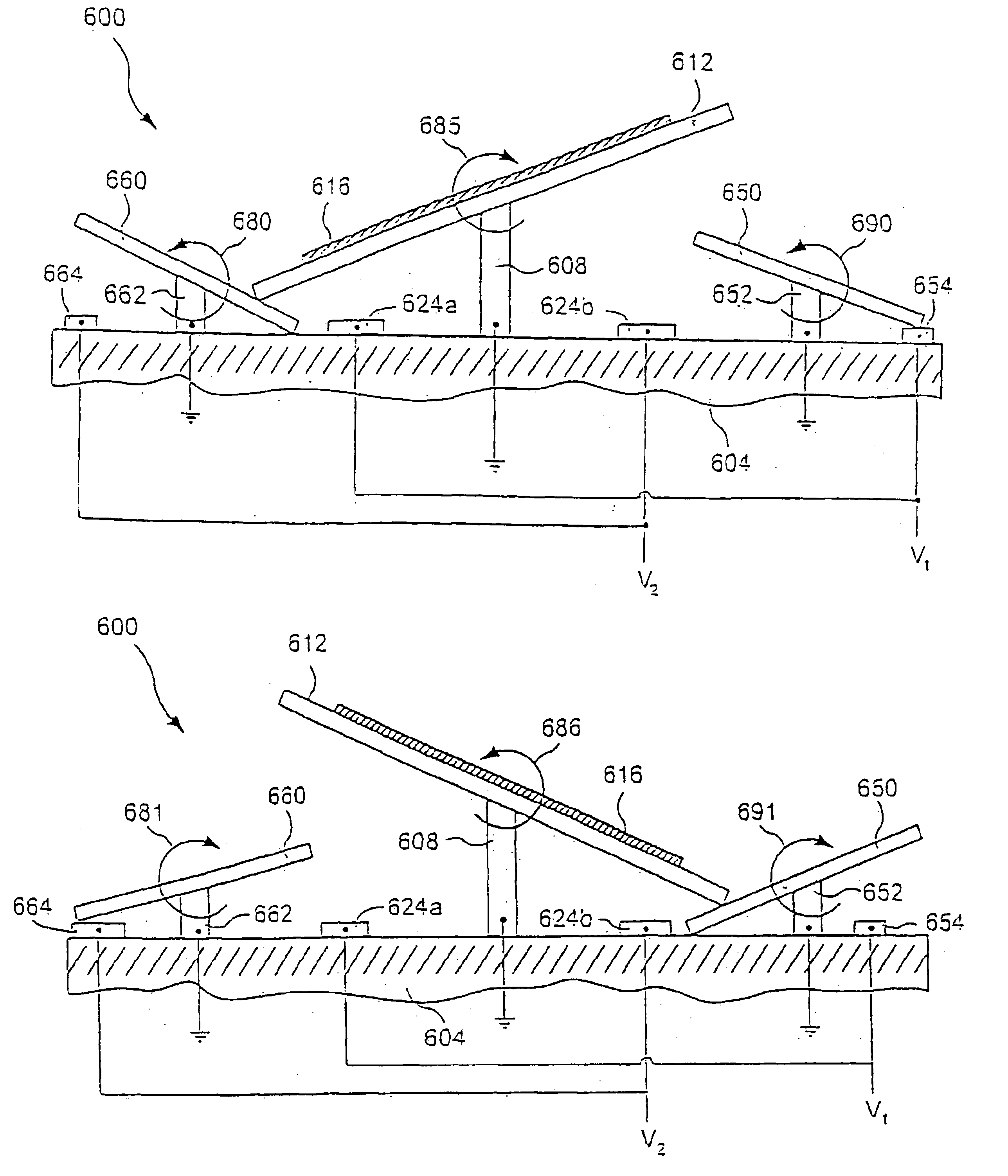
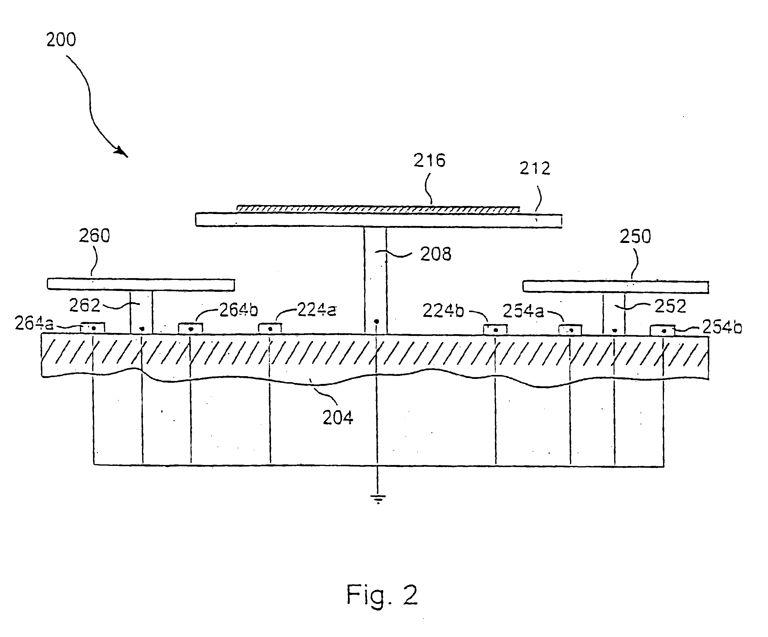
Further, some embodiments of the present invention pertain to a wavelength router including a control member disposed adjacent to a micromirror assembly. The control member can be used in relation to the micromirror assembly to overcome stiction. Other embodiments include computer readable code for execution by a microprocessor to configure plates relative to a base layer in a micromirror device. Configuring the plates comprises moving one plate to contact a base layer, while moving another plate to contact the first. In some embodiments, the contact between the two plates acts to dislodge stiction causing molecules. In other embodiments, the contact between the plates provides a lever useful for overcoming stiction related forces. In yet other embodiments, the contact between the two plates results in adding restorative forces associated with both plates in a way that overcomes stiction related forces.

Problems solved by technology

The Internet and data communications are causing an explosion in the global demand for bandwidth.
This makes it difficult and expensive to scale DWDM networks using SONET / SDH technology.
This compound process is complex, very expensive, decreases system reliability and complicates system management.
The OXC in particular is a technical challenge.
Conventional opto-mechanical switches providing acceptable optical specifications are too big, expensive and unreliable for widespread deployment.
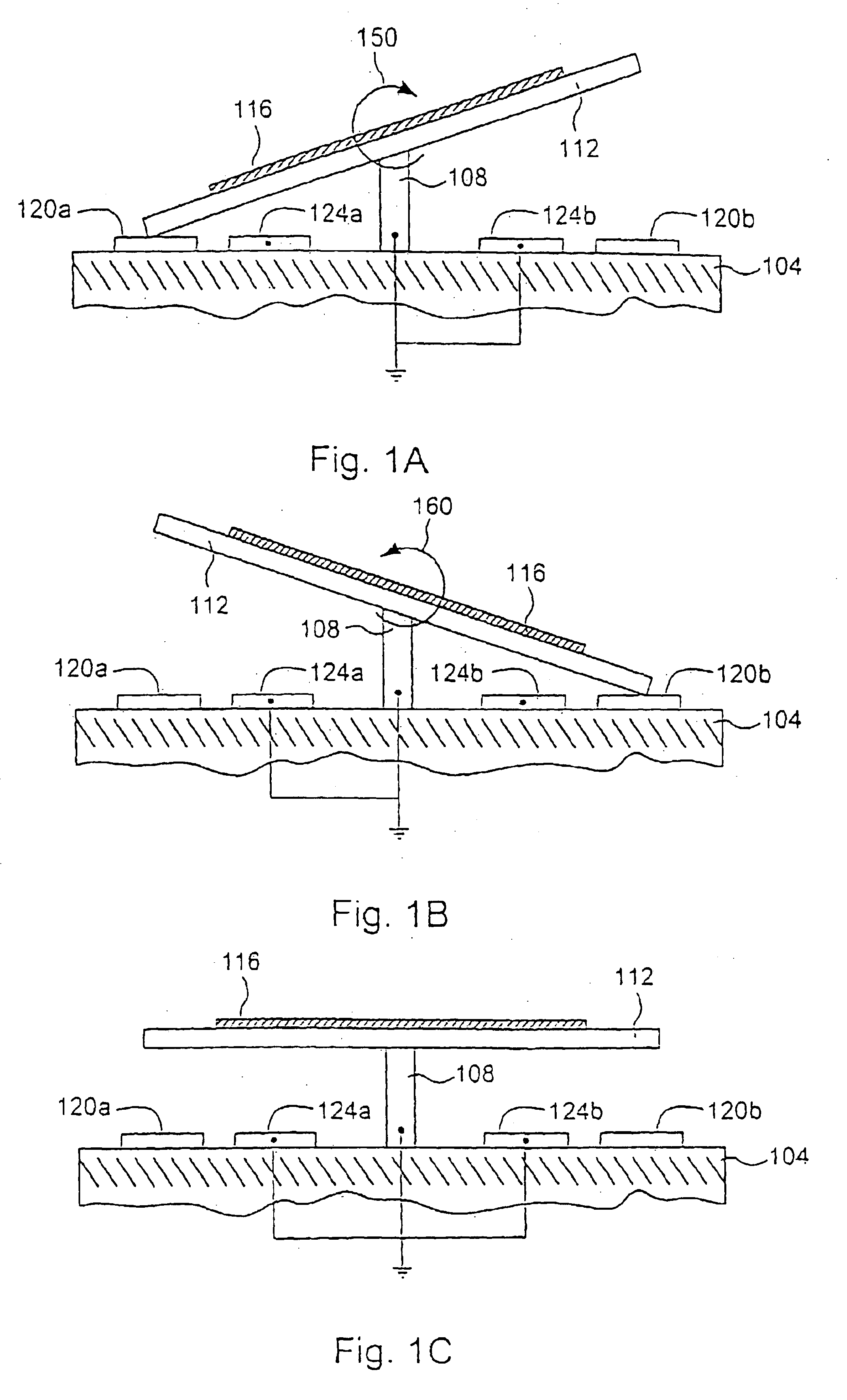
In a variety of applications, MEMS component structures may be fabricated to move in such a fashion that there is a risk of stiction between that component structure and some other aspect of the system.
Such alignment is generally complex and typically involves fixing the location of the MEMS device relative to a number of sources and targets.
If any of the micromirrors is not positioned correctly in the alignment process and / or the MEMS device is moved from the aligned position, the MEMS device will not function properly.
This ability to move micromirror 116 provides a degree of flexibility useful in aligning (including aligning, pointing,and / or steering) the MEMS device, however, alignment complexity remains significant.
Maintaining such contact increases the incidence of dormancy related stiction.
For example, it has been demonstrated that capillary forces due to an accumulation of H2O molecules at the junction increases the incidence of stiction.
Such an environment reduces the possibility of molecule accumulation at the junction.
However, such packaging is costly and prone to failure where seals break or are not properly formed.
Further, such packaging is incompatible with many types of MEMS devices.
In addition, such packaging does not reduce stiction related to charge build-up at the junction.
While there is evidence that vibrating the entire MEMS device can overcome stiction, such vibration causes temporary or even permanent misalignment of the device.
Thus, freeing an individual micromirror often requires a costly re-alignment procedure.
Even where the device is not permanently misaligned by the vibration, it is temporarily dysfunctional while the vibration is occurring.

Method used


Image

  • Systems and methods for overcoming stiction using a lever
  • Systems and methods for overcoming stiction using a lever
  • Systems and methods for overcoming stiction using a lever

Examples


third embodiment

a wavelength router, designated 10″, is illustrated with the schematic top view shown in FIG. 9. This embodiment is a further folded version of the embodiment of FIGS. 7A-7C, shown as a solid glass embodiment that uses a concave reflector 40 in place of lens 20 of FIGS. 7A-7C or lenses 20a and 20b of FIGS. 8A-8B. Light entering the wavelength router 10″ from input port 12 forms diverging beam 18, which includes the different spectral bands. Beam 18 encounters concave reflector 40, which collimates the light and directs it to reflective diffraction grating 25, where it is dispersed so that collimated beams at different wavelengths are directed at different angles back towards concave reflector 40. Two such beams are shown explicitly, one in solid lines and one in dashed lines. The beams then encounter retroreflectors 30 and proceed on a return path, encountering concave reflector 40, reflective grating 25′, and concave reflector 40, the final encounter with which focuses the beams to...


PUM


Abstract

A microstructure is provided including a base layer underlying a first and second structural plates. Operation of the microstructure is capable of overcoming stiction. Methods of operation include providing an edge of the first structural plate in contact with a contact point. A second structural plate is deflected in a way that overcomes stiction between the first structural plate and the contact point. Such deflection can include providing a prying force to lift the first structural plate or a hammering force to disturb any stiction related forces at the contact point.

Description

BACKGROUND OF THE INVENTIONThis invention relates generally to the field of micro-electrical-mechanical systems (MEMS), and in particular, to improved MEMS devices and methods for their use with fiber-optic communications systems.The Internet and data communications are causing an explosion in the global demand for bandwidth. Fiber optic telecommunications systems are currently deploying a relatively new technology called dense wavelength division multiplexing (DWDM) to expand the capacity of new and existing optical fiber systems to help satisfy this demand. In DWDM, multiple wavelengths of light simultaneously transport information through a single optical fiber. Each wavelength operates as an individual channel carrying a stream of data. The carrying capacity of a fiber is multiplied by the number of DWDM channels used. Today DWDM systems employing up to 80 channels are available from multiple manufacturers, with more promised in the future.In all telecommunication networks, ther...

Claims


Application Information

Patent Timeline
Patent Type & Authority Patents(United States)
IPC IPC(8): G02B26/08G02B6/34G02B6/35
CPCB81B3/0016G02B6/29307G02B6/2931G02B6/358G02B26/0841B81B2201/047G02B6/3518G02B6/352G02B6/3546G02B6/3548G02B6/3556G02B6/3558G02B6/356G02B6/3566G02B6/357G02B6/3584G02B6/3598B81B2203/0181
Inventor STAPLE, BEVANANDERSON, DAVID PAULMULLER, LILAC
Owner ALTERA CORP
Learn More